
Pilot type pneumatic solenoid valve

A pneumatic solenoid valve and pilot-operated technology, applied in the field of solenoid valves, can solve problems such as heavy mass, low synchronization, and slow response time, and achieve the effects of weight reduction, slow response time, and high magnetic flux utilization

Pending Publication Date: 2019-06-18
SHENYANG AEROSPACE XINGUANG GRP
View PDF0 Cites 5 Cited by
  • Summary
  • Abstract
  • Description
  • Claims
  • Application Information

AI Technical Summary

Problems solved by technology

In the traditional two-component engine, two direct-acting solenoid valves are usually used to provide fuel and oxidizer respectively, which leads to not only heavy mass of the whole engine system, but also low synchronization of opening and closing of the two solenoid valves, especially The two-component engine with large flow rate uses two direct-acting solenoid valves, and the response time is also very slow

Method used


Image

  • Pilot type pneumatic solenoid valve
  • Pilot type pneumatic solenoid valve
  • Pilot type pneumatic solenoid valve

Examples


Embodiment

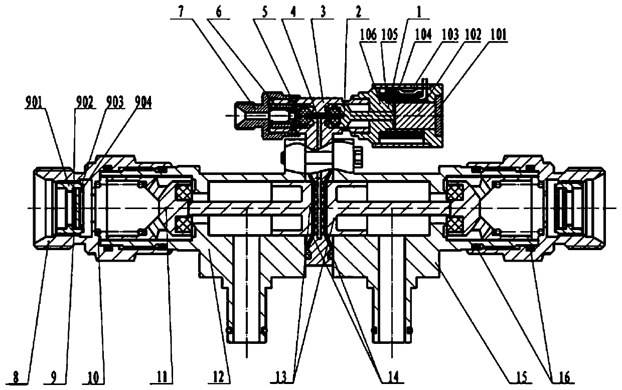
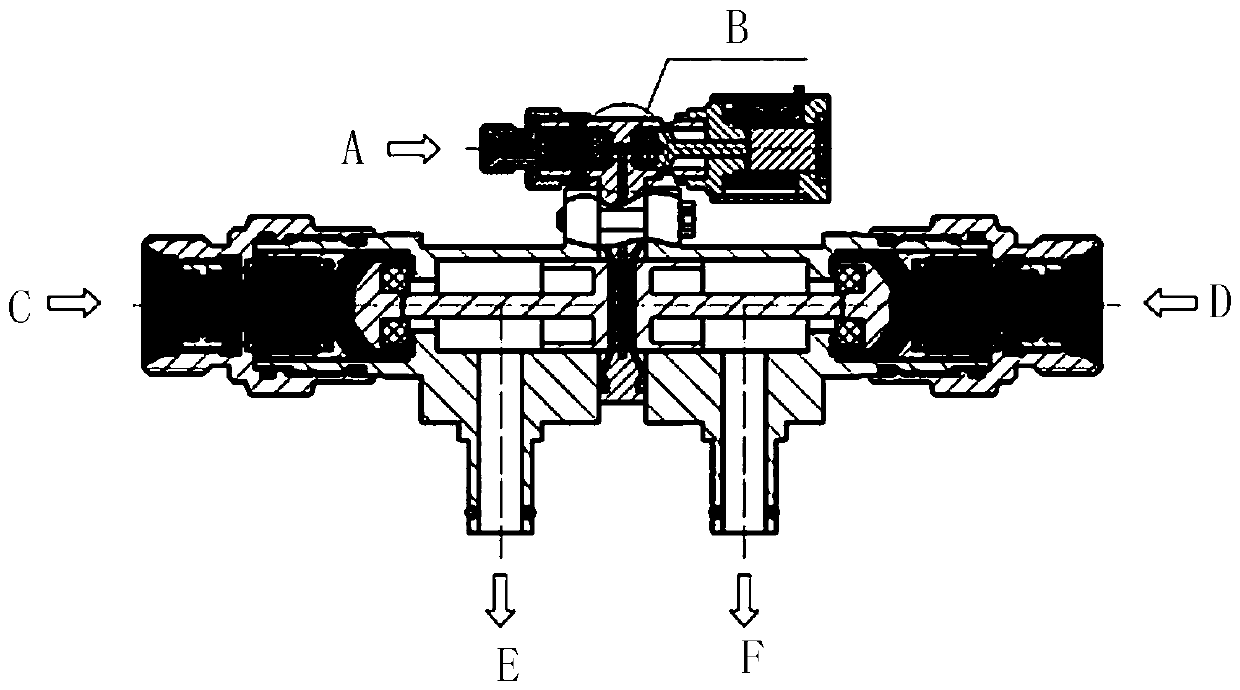
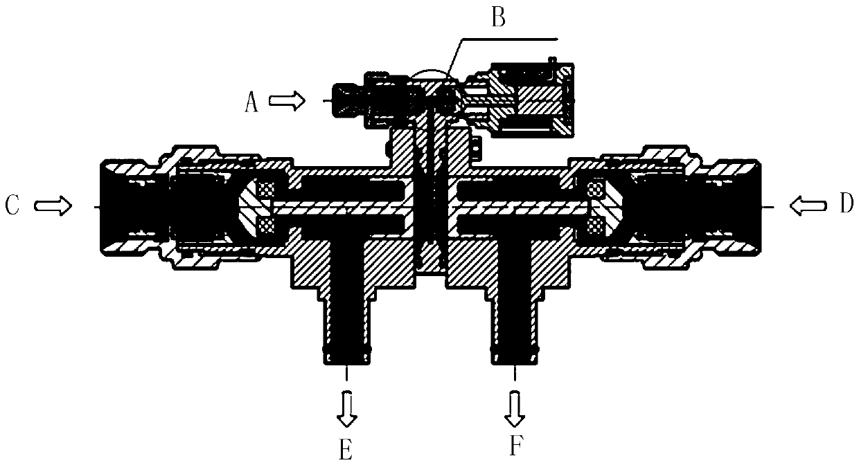
[0018] As shown in the figure, a pilot-operated pneumatic solenoid valve includes a solenoid valve assembly 1, an air push rod 2, a bracket 3, an air valve core 5, a liquid valve core 11, a filter screen assembly 9, a connecting rod 4, and an air circuit spring 6 , Gas nozzle 7, liquid nozzle 8, liquid spring 10, liquid push rod 13, liquid housing Y12, liquid housing R15, sealing rubber ring 16 and rubber pad 14.

[0019] The solenoid valve assembly 1 is a magnetic field forming mechanism, including a housing 106 welded by magnetic materials and stainless steel, a coil 105 wound on the outer wall of the housing for generating a magnetic field, and a casing that is placed outside the coil to form a magnetic field circuit 103, the magnetic valve core 102 set in motion in the housing, the magnetic isolation spacer 104 providing the magnetic isolation effect is installed at one end of the magnetic valve core 102, and the spiral ring 101 is installed at the end of the housing for co...


PUM


Abstract

The invention relates to a pilot type pneumatic solenoid valve. The pilot type pneumatic solenoid valve comprises a solenoid valve component, a gas pushing rod, a bracket, a gas valve core, a liquid valve core, a filtering net component, a gas path spring, a connecting rod, a gas connecting nozzle, liquid path connecting nozzles, liquid path springs, liquid path pushing rods, liquid shell Y, a liquid shell R, sealing rubber rings and rubber mats; a magnetic valve in the solenoid valve component is moved to the left side under the action of electromagnetic force; the gas pushing rod, the connecting rod and the gas valve are pushed to move to the left side together so that pilot gas enters the cavity of the bracket; through holes which are distributed uniformly are formed in the cavity of the bracket; the pilot gas makes the rubber mats on the two sides expand by a certain distance from the through holes in the cavity of the bracket; under the action of the pressure of the pilot gas, theliquid pushing rods on the two sides of the bracket respectively push the liquid valve cores on the two sides to move to open liquid inlets in the two sides, so that a liquid medium flows to outlets.The pilot type pneumatic solenoid valve has the characteristics of compact structure, light weight, high synchronism, short response time and the like, and is suitable for propulsion systems of satellites, weapons and the like.

Description

technical field [0001] The invention relates to a solenoid valve, in particular to a pilot type pneumatic solenoid valve. Background technique [0002] Pilot-operated pneumatic solenoid valve is an important part of attitude and orbit control systems in satellites, weapons, and electric propulsion fields. In the traditional two-component engine, two direct-acting solenoid valves are usually used to provide fuel and oxidizer respectively, which leads to not only heavy mass of the whole engine system, but also low synchronization of opening and closing of the two solenoid valves, especially The two-component engine with a large flow rate uses two direct-acting solenoid valves, and the response time is also very slow. Contents of the invention [0003] The technical problem to be solved by the present invention is to provide a pilot solenoid valve, which has the characteristics of compact structure, light weight, high synchronization and fast response time, and is suitable f...

Claims


Application Information

Patent Timeline
IPC IPC(8): F16K11/16F16K31/06F16K31/16
Inventor 杨阳李强胡森林启明侯建魁
Owner SHENYANG AEROSPACE XINGUANG GRP
Learn More