Contact arc extinguishing system of circuit breaker

A circuit breaker and arc extinguishing technology, applied in the directions of circuit breaker contacts, circuit breaker parts, circuits, etc., can solve the problems that the air outlet cannot be in the arc movement, the discharge speed is not as fast as the generation speed, and the exhaust channel cannot be fully utilized. , to achieve the effect of accelerating the arc transfer speed, simplifying the equipment and reducing the cost

Pending Publication Date: 2019-06-18
SHANGHAI ELECTRICAL APP RES INST +1
View PDF1 Cites 1 Cited by
  • Summary
  • Abstract
  • Description
  • Claims
  • Application Information

AI Technical Summary

Problems solved by technology

[0003] The structure of the common molded case circuit breaker interrupter system is as follows: figure 1 As shown, its composition in the circuit breaker is as Figure 2a As shown, this type of arc extinguishing chamber includes arc partitioning walls 101 on both sides of the arc extinguishing grid 102, and an arc blocking seat 103 facing the contact system, and the air outlet is located on the side of the arc extinguishing chamber facing the terminal. The shortcoming of the circuit breaker arc extinguishing chamber is that it does not make full use of the internal cavity volume of the circuit breaker, and the arc extinguishing capacity is limited
[0007] exist Figure 2b In th

Method used


Image

  • Contact arc extinguishing system of circuit breaker
  • Contact arc extinguishing system of circuit breaker
  • Contact arc extinguishing system of circuit breaker

Examples


Embodiment Construction

[0040] Below in conjunction with specific embodiment, further illustrate the present invention.

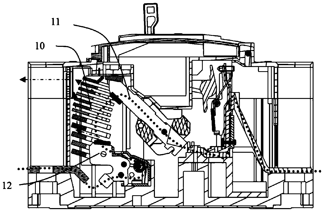
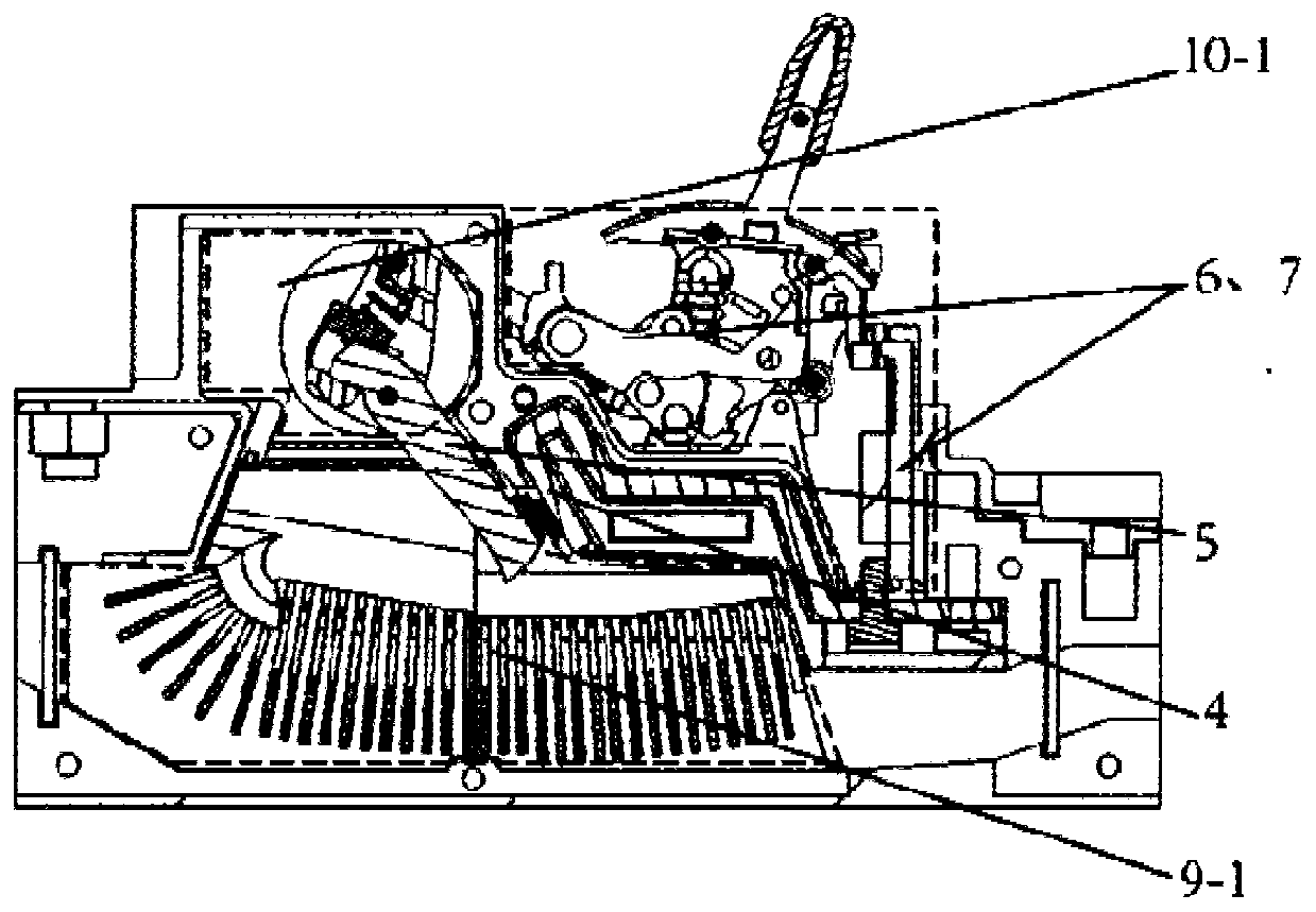
[0041] combine image 3 and Figure 4 , The present invention provides a contact arc extinguishing system of a circuit breaker, including an arc extinguishing system 20, a moving contact 22, a static contact 23 and the like. The moving contact 22 and the static contact 23 are arranged opposite to each other to form a contact system; the arc extinguishing system 20 is arranged under the contact system and is located at the bottom of the housing 25, and the arc extinguishing system 20 has a side with an arc strike groove Facing the contact system, the back of the arc extinguishing system 20 is facing the inner surface of the bottom surface of the housing 25. The left and right sides of the arc extinguishing system 20 are provided with exhaust ports 28. The arc extinguishing system 20 and the corresponding exhaust channels occupy the space of the housing 25. The lower space. A zer...


PUM


Abstract

The invention provides a contact arc extinguishing system of a circuit breaker. The contact arc extinguishing system comprises a left side arc extinguishing chamber and a right side arc extinguishingchamber which are oppositely arranged, by taking a vertical line vertical to the bottom surface of a shell of the circuit breaker as a benchmark, the left side arc extinguishing chamber deflects towards the left, the right side arc extinguishing chamber deflects towards the right, and exhaust ports are formed in the left end part of the left side arc extinguishing chamber and the right end part ofthe right side arc extinguishing chamber respectively; an arc extinguishing grid sheet is arranged in the left side arc extinguishing chamber and the right side arc extinguishing chamber respectively, the arc extinguishing grid sheet in the left side arc extinguishing chamber deflects towards the left, and the arc extinguishing grid sheet in the right side arc extinguishing chamber deflects towards the right; and a separation arc extinguishing sheet is arranged between the left side arc extinguishing chamber and the right side arc extinguishing chamber. The contact arc extinguishing system provided by the invention realizes a double air outlet design on a single breakpoint moulded case circuit breaker, the separation grid sheet is arranged between the grid sheets, track of an electric arcis separated, and the electric arc is respectively guided to the two air outlets by combining arc striking sheets at the two sides, so that high temperature and high pressure gas is discharged to theoutside of the shell as soon as possible. The contact arc extinguishing system provided by the invention greatly increases available cavity volume of each arc extinguishing chamber, quantity, depthsand sectional areas of the grid sheets of the arc extinguishing chambers can be increased respectively, and capacity of the arc extinguishing system is greatly improved.

Description

technical field [0001] The invention relates to an arc extinguishing chamber structure, in particular to a contact arc extinguishing system applied to a low-voltage circuit breaker. Background technique [0002] The arc extinguishing chamber is the core component in the arc extinguishing system of the circuit breaker, which is used to limit the spatial position of the arc and accelerate the extinction of the arc. A common arc extinguishing chamber is composed of arc extinguishing grids and side plates, and its arc extinguishing capacity is proportional to the number, depth and cross-sectional area of ​​the grids. So, how to arrange an arc extinguishing chamber with a larger arc extinguishing capacity in the limited space of the circuit breaker? This is a difficult problem that all personnel engaged in the research and development of low-voltage circuit breakers must face. In addition, the arrangement angle of the arc extinguishing grid is also very critical, because the ai...

Claims


Application Information

Patent Timeline
IPC IPC(8): H01H73/18H01H73/04H01H9/34
Inventor 张森林孙吉升
Owner SHANGHAI ELECTRICAL APP RES INST
Why Eureka
Try Eureka