Method of producing solar modules by the roller laminate process

A technology for solar cells and modules, applied in the fields of electrical components, chemical instruments and methods, lamination, etc., can solve the problem of not being able to sufficiently prepare composites with thin-layer solar cell modules on an industrial scale by itself.

Inactive Publication Date: 2008-08-06
KURARAY EURO GMBH
View PDF27 Cites 15 Cited by
  • Summary
  • Abstract
  • Description
  • Claims
  • Application Information

AI Technical Summary

Problems solved by technology

The known methods for producing solar modules with solar cells buried between PVB films are not suffic

Method used


Image

  • Method of producing solar modules by the roller laminate process
  • Method of producing solar modules by the roller laminate process

Examples


Embodiment

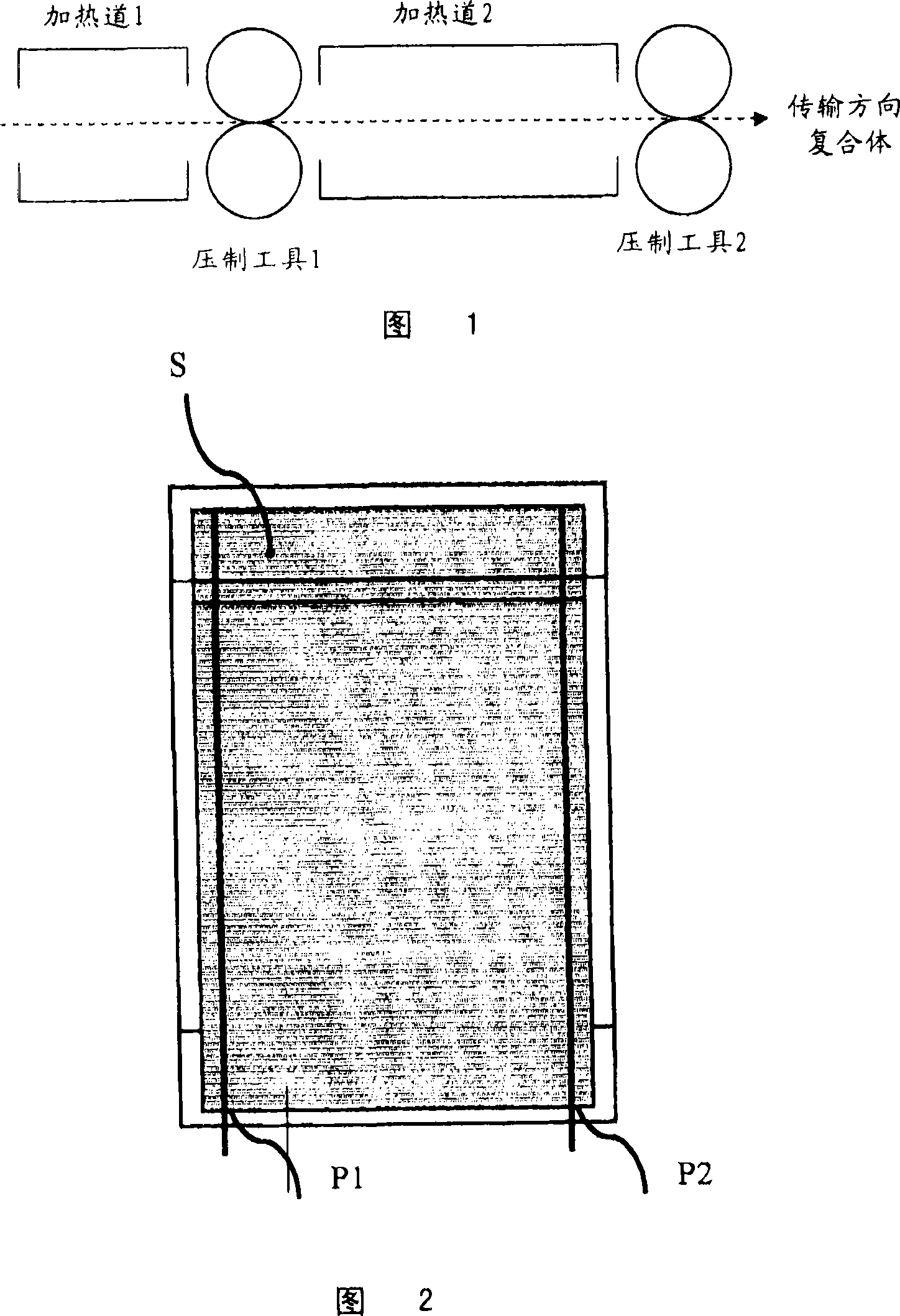
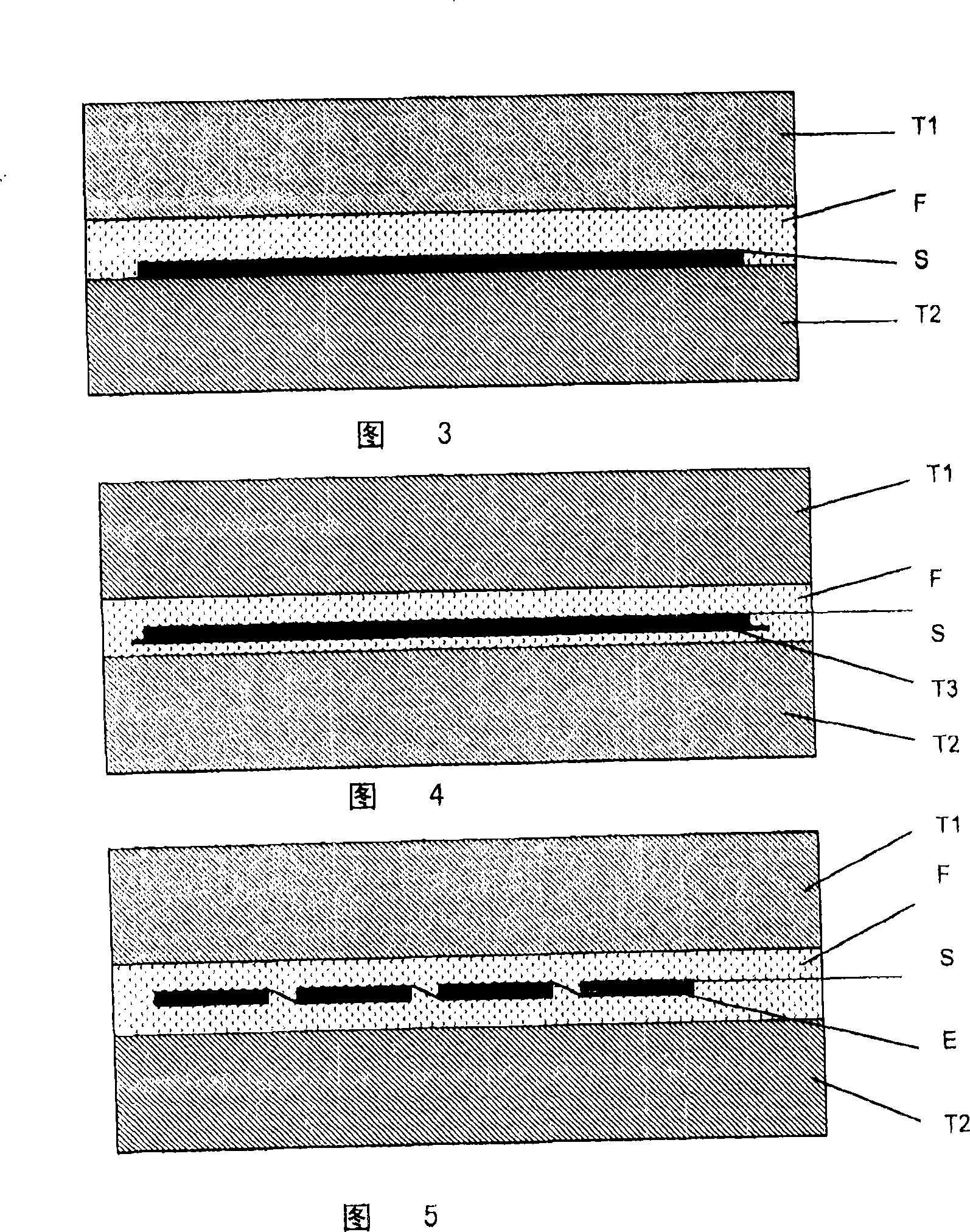
[0044] Thin layers were pressed at a temperature of 90 °C (measured after the last pressing tool) and a linear pressure of 35 N / mm each at a feed rate of 3 m / min in the apparatus shown in Figure 1 Module, the thin-layer module has dimensions of 30 cm long x 20 cm wide and a glass thickness of 3.2 mm, and also has two conductive strips with a longitudinal distance of 20 mm from the edge, a width of 2 mm, and a thickness of about 250 μm. The running direction of the complex is chosen so that the outlet of the conductive channel from the module is at the rear and pressed last. As a softener-containing polyvinyl acetal film, roughness R Z Membrane of the Trosifol HR 100 type (Kuraray Europe GmbH) of about 100 μm.

[0045] The line pressure of the pressing tool is to be reduced to the dead weight of the upper roll over the first 10 mm and the last 30 mm of the ply.

[0046] A slightly cloudy, bubble-free laminate was obtained.

[0047] This turbidity can be completely eliminated...


PUM

PropertyMeasurementUnit
Roughness valueaaaaaaaaaa

Abstract

The invention relates to a layer body consisting of a first carrier and a second carrier on which at least one solar cell unit is arranged by laminating at least one interposed film based on softener-containing polyvinyl acetal , and a method for producing a solar cell module by pressing the layer between at least one roller pair at a temperature of 50 to 150°C.

Description

technical field [0001] The present invention relates to a process for producing thin-film solar cell modules using a roll lamination method using polyvinyl butyral (PVB)-based films. Background technique [0002] Thin-film solar cell modules generally consist of a photosensitive semiconductor layer (referred to below as a solar cell) which is applied to a mostly transparent sheet, for example by evaporation, vapor deposition, sputtering or wet deposition An optionally likewise transparent covering is arranged on top and for protection against external influences. The solar cells are often laminated by means of an optionally transparent adhesive between a glass pane and a cover pane, for example made of glass. The adhesive must completely enclose the solar cell unit, must be UV stable and completely free of bubbles after the lamination process. [0003] As transparent adhesives, generally cured casting resins or crosslinkable ethylene-vinyl acetate (EVA)-based systems are u...

Claims


Application Information

Patent Timeline
IPC IPC(8): H01L31/18
CPCB29C65/10B29C65/14B29C65/1412B29C65/1425B29C65/4815B29C65/5057B29C66/45B29C66/71B29C66/723B29C66/72321B29C66/72326B29C66/73161B29C66/73751B29C66/73755B29C66/7392B29C66/83413B29C66/91216B29C66/91221B29C66/91411B29C66/91421B29C66/91423B29C66/91445B29C66/919B29C66/9241B29C66/92445B29C66/929B29C66/9292B29C2035/0822B29K2029/14B29K2105/0038B29K2995/0072B29L2009/00B32B17/10036B32B17/10247B32B17/10761B32B17/10816B32B17/10871B32B37/0053B32B37/18B32B2305/34B32B2309/12B32B2457/12H01L31/048H01L31/0488H01L31/18Y02E10/50
Inventor A·卡品斯基B·科尔
Owner KURARAY EURO GMBH
Why Eureka
Try Eureka