Photovoltaic module lamination chamber, lamination device and lamination method

A photovoltaic module and lamination equipment technology, applied in the field of solar cells, can solve the problems of high production cost and low efficiency, and achieve the effects of reducing production time and energy consumption, reducing the probability of component fragments, and saving use costs

Active Publication Date: 2019-06-18
YINGLI ENERGY CHINA
View PDF10 Cites 0 Cited by
  • Summary
  • Abstract
  • Description
  • Claims
  • Application Information

AI Technical Summary

Problems solved by technology

[0004] The purpose of the present invention is to provide a photovoltaic module lamination room to solve the problem

Method used


Image

  • Photovoltaic module lamination chamber, lamination device and lamination method
  • Photovoltaic module lamination chamber, lamination device and lamination method
  • Photovoltaic module lamination chamber, lamination device and lamination method

Examples


Embodiment Construction

[0035] In order to make the technical problems, technical solutions and beneficial effects to be solved by the present invention clearer, the present invention will be further described in detail below in conjunction with the accompanying drawings and embodiments. It should be understood that the specific embodiments described here are only used to explain the present invention, not to limit the present invention.

[0036] The present invention will be further described in detail below in conjunction with the accompanying drawings and specific embodiments.

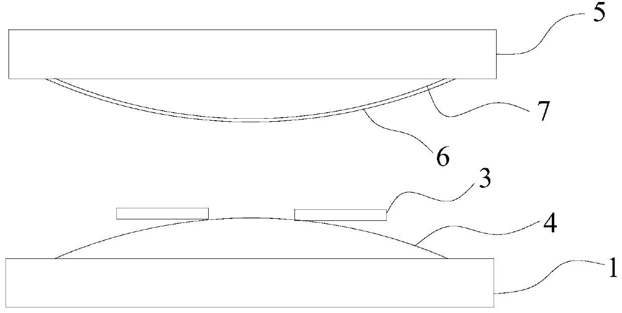
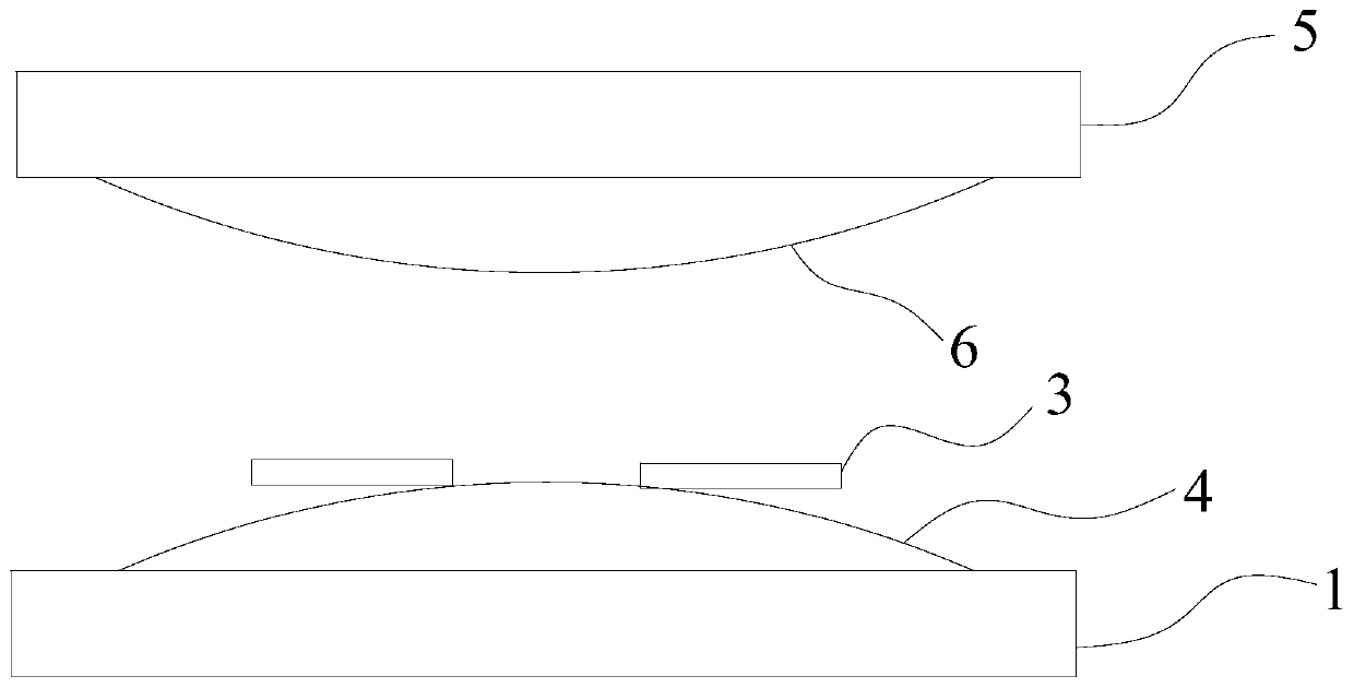
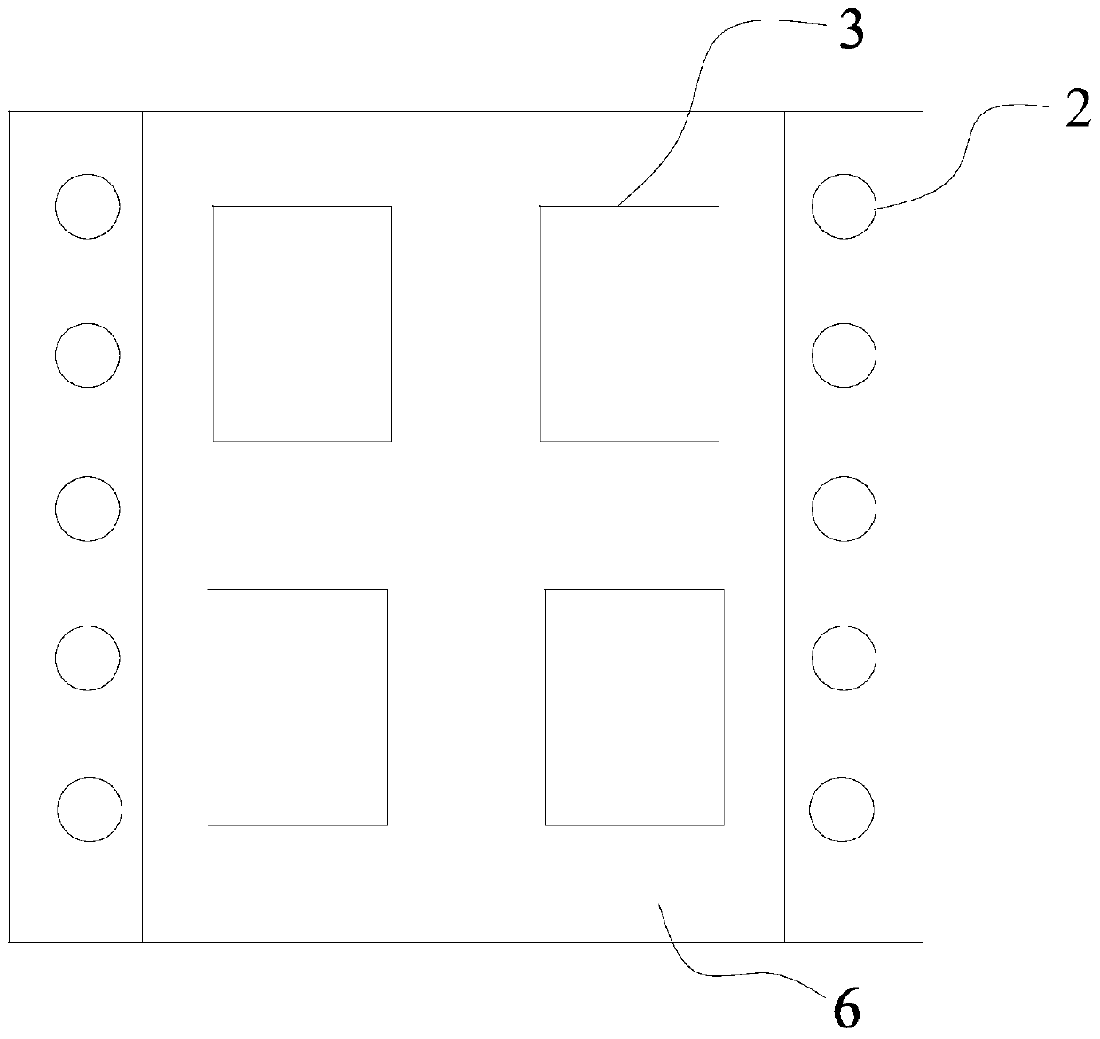
[0037] refer to figure 2 and Figure 4 , an embodiment of the present invention provides a photovoltaic module lamination chamber, including: an upper chamber casing 5, a lower chamber casing 1, a heating plate (not shown in the figure), a laminated lower cloth 4 and a laminated upper cloth 6 . The lower chamber housing 1 can be airtightly connected with the upper chamber housing 5, and the bottom is provided with an a...


PUM


Abstract

The invention relates to a photovoltaic module lamination chamber, lamination device and lamination method. The photovoltaic module lamination chamber comprises: an upper chamber shell; a lower chamber shell that can be hermetically connected with the upper chamber shell and is provided with an air suction hole at the bottom; a heating plate disposed in the lower chamber shell and not covering theair suction hole; lower lamination cloth, which is made of an impermeable material, is fixed to the lower chamber shell, covers the heating plate, is used for placing a photovoltaic module and does not cover the air suction hole; and upper lamination cloth, which is made of the impermeable material, is fixed to the upper chamber shell, and can cover the air suction hole when a negative pressure is formed in the lamination chamber to generate a pressure for the photovoltaic module. By adjusting the equipment structure, the lamination chamber may use no silica gel plate.

Description

technical field [0001] The invention relates to the field of solar cells, in particular to a photovoltaic module lamination chamber, lamination equipment and a lamination method. Background technique [0002] The lamination process of photovoltaic modules is a key link in the production of modules. The laminator is composed of several parts such as pneumatic system, vacuum system, heating system, transportation system, and control system. The main laminated parts include the silicone plate, the upper chamber shell and the lower heating plate. [0003] At present, the heating temperature of the laminator is basically set at 140-150°C, the evacuation time is 5-8 minutes, the pressurization is 1-2 minutes, and the curing time is 9-15 minutes. The traditional lamination process is divided into vacuuming, heating components, and curing. three parts. The lamination process is to first pass the stacked components through the Teflon varnished cloth on the heating plate of the lowe...

Claims


Application Information

Patent Timeline
IPC IPC(8): H01L21/67H01L31/18
CPCY02P70/50
Inventor 苗蕾张建旗杨燕刘凯辉
Owner YINGLI ENERGY CHINA
Why Eureka
Try Eureka