
Bearing substrate and manufacturing method thereof, flexible substrate and manufacturing method thereof, and display device

A technology of a carrier substrate and a manufacturing method, which is applied in the fields of identification devices, nonlinear optics, climate sustainability, etc., can solve the problems of complicated operation, high cost, and reduce the adhesion between the flexible substrate and the carrier substrate, and achieves a high level of improvement. The effect of production quality, reduction of peeling difficulty and peeling cost

Active Publication Date: 2019-06-18
BOE TECH GRP CO LTD
View PDF8 Cites 4 Cited by
  • Summary
  • Abstract
  • Description
  • Claims
  • Application Information

AI Technical Summary

Problems solved by technology

[0004] In related technologies, lasers are usually used to peel off the flexible substrate from the carrier substrate, but this method is complex in operation, high in cost, and the flexible substrate is easily damaged, which reduces the production yield of the flexible substrate; When formed on the carrier substrate, by reducing the adhesive force between the flexible substrate and the carrier substrate, it is convenient to use mechanical force to peel off the flexible substrate from the carrier substrate, but due to the adhesion between the flexible substrate and the carrier substrate The resultant force is reduced. Therefore, during the production process of the flexible substrate, the flexible substrate is easy to move on the carrier substrate, which easily affects the production quality of the flexible substrate and reduces the production yield of the flexible substrate.

Method used


Image

  • Bearing substrate and manufacturing method thereof, flexible substrate and manufacturing method thereof, and display device
  • Bearing substrate and manufacturing method thereof, flexible substrate and manufacturing method thereof, and display device
  • Bearing substrate and manufacturing method thereof, flexible substrate and manufacturing method thereof, and display device

Examples


Embodiment Construction

[0057] Example embodiments will now be described more fully with reference to the accompanying drawings. Example embodiments may, however, be embodied in many forms and should not be construed as limited to the embodiments set forth herein; rather, these embodiments are provided so that this application will be thorough and complete, and will fully convey the concept of example embodiments to those skilled in the art. The same reference numerals in the drawings denote the same or similar structures, and thus their detailed descriptions will be omitted.

[0058]Although relative terms such as "upper" and "lower" are used in this specification to describe the relative relationship of one component of an icon to another component, these terms are used in this specification only for convenience, for example, according to the description in the accompanying drawings directions for the example described above. It will be appreciated that if the illustrated device is turned over so...


PUM

PropertyMeasurementUnit
sizeaaaaaaaaaa
sizeaaaaaaaaaa

Abstract

The present invention relates to the technical field of display, especially to a bearing substrate and a manufacturing method thereof, a flexible substrate and a manufacturing method thereof, and a display device. The bearing substrate comprises: a substrate comprising a first surface and a second surface opposite to the first surface; a bonding portion arranged at the second surface and comprising magnetic particles, wherein the magnetic particles can rotate under the action of an external magnetic field, the magnetic particles comprise a first portion and a second portion, when the first portion faces one side far away from the first surface, the binding force between the bonding portion and the flexible substrate can be weakened, and when the second portion faces one side far away fromthe first surface, the binding force between the bonding portion and the flexible substrate is enhanced. The bearing substrate and the manufacturing method thereof can reduce the stripping difficultyand the stripping cost of the flexible substrate and the bearing substrate while improving the manufacturing quality of the flexible substrate.

Description

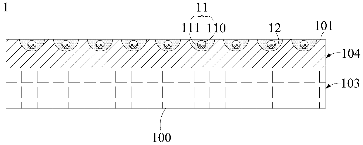
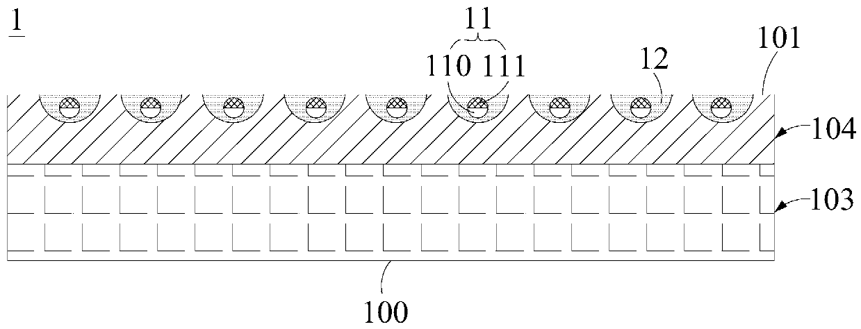
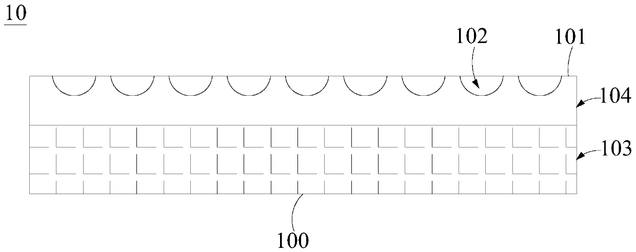
technical field [0001] The present application relates to the field of display technology, in particular, to a carrier substrate, a method for manufacturing the carrier substrate, a flexible substrate, a method for manufacturing the flexible substrate, and a display device. Background technique [0002] With the development of display technology, display products are increasingly diversified and humanized. Among them, flexible display is an important development direction. [0003] At present, the manufacturing method of flexible substrates generally includes: using a rigid carrier substrate as a support, temporarily forming a flexible substrate on the carrier substrate, then fabricating a functional layer on the flexible substrate to obtain a flexible substrate, and finally combining the carrier substrate with the flexible substrate. The substrate is peeled off. [0004] In related technologies, lasers are usually used to peel off the flexible substrate from the carrier s...

Claims


Application Information

Patent Timeline
Patent Type & Authority Applications(China)
IPC IPC(8): H01L51/56H01L27/32G02F1/1333G09F9/30
CPCG02F1/133305G02F1/1303Y02E10/549Y02P70/50H10K71/80H10K77/111H10K59/1201H10K2102/311G03F7/09H10K59/12H10K71/00
Inventor 代青
Owner BOE TECH GRP CO LTD
Learn More