Metasurface rectification antenna array for space electromagnetic wave detection and energy collection

An energy harvesting and rectifying antenna technology, which is applied to antenna unit combinations, antennas, and loop antennas with different polarization directions, can solve problems such as space energy collection that is not suitable for low power

Active Publication Date: 2019-06-18
SICHUAN UNIV
View PDF10 Cites 13 Cited by
  • Summary
  • Abstract
  • Description
  • Claims
  • Application Information

AI Technical Summary

Problems solved by technology

However, the proposed rectenna is only suitable for receiving medium and high-power

Method used


Image

  • Metasurface rectification antenna array for space electromagnetic wave detection and energy collection
  • Metasurface rectification antenna array for space electromagnetic wave detection and energy collection
  • Metasurface rectification antenna array for space electromagnetic wave detection and energy collection

Examples


Embodiment 1

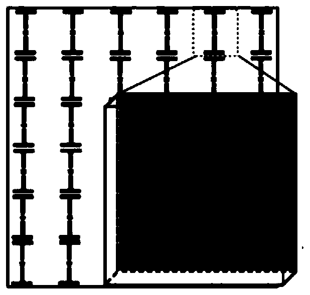
[0031] This embodiment provides a metasurface rectenna array for space electromagnetic wave detection and energy collection, and its structural diagram is as follows Figure 5 As shown, it includes a metasurface receiving antenna array 1, two sets of rectifying circuit arrays 2, an energy distribution circuit 3, a load 4 and a dielectric substrate 5; the metasurface receiving antenna array 1 is located on the upper surface of the dielectric substrate 5, and two sets of rectifying circuit arrays 2 , the energy distribution circuit 3 and the load 4 are located on the lower surface of the dielectric substrate 5;

[0032] The metasurface receiving antenna array 1 is a 3×4 metasurface array structure composed of multi-frequency resonant ring units; the working mode of the resonant ring units in each row in the metasurface array structure is the same, and every two adjacent resonant ring units are one The metasurface receiving unit; the resonant ring unit of each column in the metas...

Embodiment 2

[0042] This embodiment provides a metasurface rectenna array for space electromagnetic wave detection and energy collection, and its structural diagram is as follows Figure 8 As shown, it includes a metasurface receiving antenna array 1, two sets of rectifying circuit arrays 2, an energy distribution circuit 3, a load 4 and a dielectric substrate 5; the metasurface receiving antenna array 1 is located on the upper surface of the dielectric substrate 5, and two sets of rectifying circuit arrays 2 , the energy distribution circuit 3 and the load 4 are located on the lower surface of the dielectric substrate 5;

[0043] The metasurface receiving antenna array 1 is a 4 × 3 metasurface array structure composed of multi-polarized resonant ring units; the working mode of the resonant ring units in each row in the metasurface array structure is the same, and every two adjacent resonant ring units are A metasurface receiving unit; the working modes of the resonant ring units in adjace...


PUM


Abstract

The invention discloses a metasurface rectification antenna array for space electromagnetic wave detection and energy collection, and belongs to the technical field of a space energy collection rectification antenna array. On the basis of a multi-mode metasurface structure, a full-wave rectification topological structure is employed, and electromagnetic wave energy in various modes in a space is collected by reasonably arranging rectification antenna array layout. Compared with a traditional rectification antenna, the low-power radio frequency energy can be efficiently collected by the metasurface antenna array, and the metasurface rectification antenna array has greater development advantages; moreover, the full-wave rectification circuit array can be used for efficiently converting the low-power radio-frequency energy to DC energy, and the radio frequency energy in different modes is classified by an energy allocation circuit and then is supplied to different loads; and the electromagnetic wave energy of different frequencies or polarization in the space is detected by judging whether a DC power output exists in the load or not, the radio frequency energy is classified and collected, and the metasurface rectification antenna array can be widely applied to space electromagnetic wave frequency, polarization detection and space wireless energy collection.

Description

technical field [0001] The invention belongs to the technical field of rectifying antenna arrays for space energy collection, and in particular relates to a metasurface rectifying antenna array for space electromagnetic wave detection and energy collection. Background technique [0002] With the rapid development of mobile communication technology, a large amount of electromagnetic waves are radiated into space. Therefore, there are a large number of different forms of electromagnetic waves in the environment. If there are a large number of electromagnetic waves in the environment without control, it will cause electromagnetic environmental pollution. This will not only interfere with electronic equipment and affect normal work, but also cause diseases and other injuries to the human body. Considering the space electromagnetic wave safety standards, the power density of electromagnetic waves in space cannot exceed 1mw / cm 2 . In order to collect electromagnetic waves in s...

Claims


Application Information

Patent Timeline
IPC IPC(8): H01Q23/00H01Q21/24H01Q7/00H01Q15/00H01Q5/10H01Q5/20H01Q5/314
Inventor 卢萍黄卡玛杨阳朱铧丞
Owner SICHUAN UNIV
Why Eureka
Try Eureka