RFID tag using a surface insensitive antenna structure

a surface-sensitive, antenna-based technology, applied in the direction of antenna supports/mountings, burglar alarms by hand-held items removal, etc., can solve the problems of inacceptable variations in the impedance of the rfid device, packaging material variations, etc., to achieve convenient lamination flexibility, improve performance, and facilitate manufacturing

Inactive Publication Date: 2005-07-05
AVERY DENNISON CORP
View PDF43 Cites 119 Cited by
  • Summary
  • Abstract
  • Description
  • Claims
  • Application Information

AI Technical Summary

Benefits of technology

[0022]In one preferred embodiment, the label stock is a foam material as a foam material provides electrical as well as mechanical manufacturing advantages in providing a more efficient performance than some other materials such as cardboard, within relatively short, compact dimensions than would otherwise be required to produce the same results. The foam material also acts as a dielectric medium, as discussed further below, that makes for easier manufacturing and permits laminating flexibility and less cost than found with solid materials such as polypropelene which are fairly inflexible and costly in manufacturing and use.
[0023]Also, the manufacturing advantages of uniform tabs are seen to greatest advantage when the labels or tab sets as they are being manufactured on a web medium, are arranged on such medium in a regular array, such as an orthogonal row-and-column array. Just as the preferred geometry involves one or more rows of tabs arrayed along the machine direction of a web of flexible dielectric stock, it is preferred that each set of uniform tabs be circumscribed by a well defined area of the web; most preferably this circumscribing area substantially takes the form of a rectangle.
[0024]Likewise, it is preferred that the ground plane or radio frequency reflecting member of the antenna structure or tag be formed in association with the tag itself for better space and manufacturing efficiency using the web manufacturing process. In one method, the ground plane is formed or provided separately from the formation of the tabs on the long flexible web. In this case, the separately produced ground plane must later be associated with and properly positioned when the tag is placed on its desired packaging.
[0025]In another method, the ground plane is formed on the same web as the tabs, preferably along the machine direction of the web. The antenna tabs and the ground plane may be separated by a fold line, which may be a scored line on the web, for ease in application of the label to packaging. In this method, the antenna structure of the tag and its associated ground plane elements are formed together in a known and fixed spatial relationship and handled as a single unit for application to the desired packaging. In application, the tag is placed on a side of the packaging along an edge. In this position, the tag can be folded along a score line so that the antenna structure portion of the tag remains on the outside surface panel of the package, while the ground plane portion is positioned on the inside surface of the panel of the package opposite the antenna tabs to provide a radio frequency reflective ground plane. Intermediate the antenna tabs and the ground plane element of the tab is sandwiched the side of the packaging, which may be used by the label as a dielectric between these two label elements for better label operation.

Problems solved by technology

A disadvantage of this embodiment is that variability of the packaging material, such as its structure and its dielectric constant (the dielectric constant is the amount of permissivity of a particular material).
This variability in turn can lead to unacceptable variations in the impedance of the RFID device.

Method used


Image

  • RFID tag using a surface insensitive antenna structure
  • RFID tag using a surface insensitive antenna structure
  • RFID tag using a surface insensitive antenna structure

Examples


Embodiment Construction

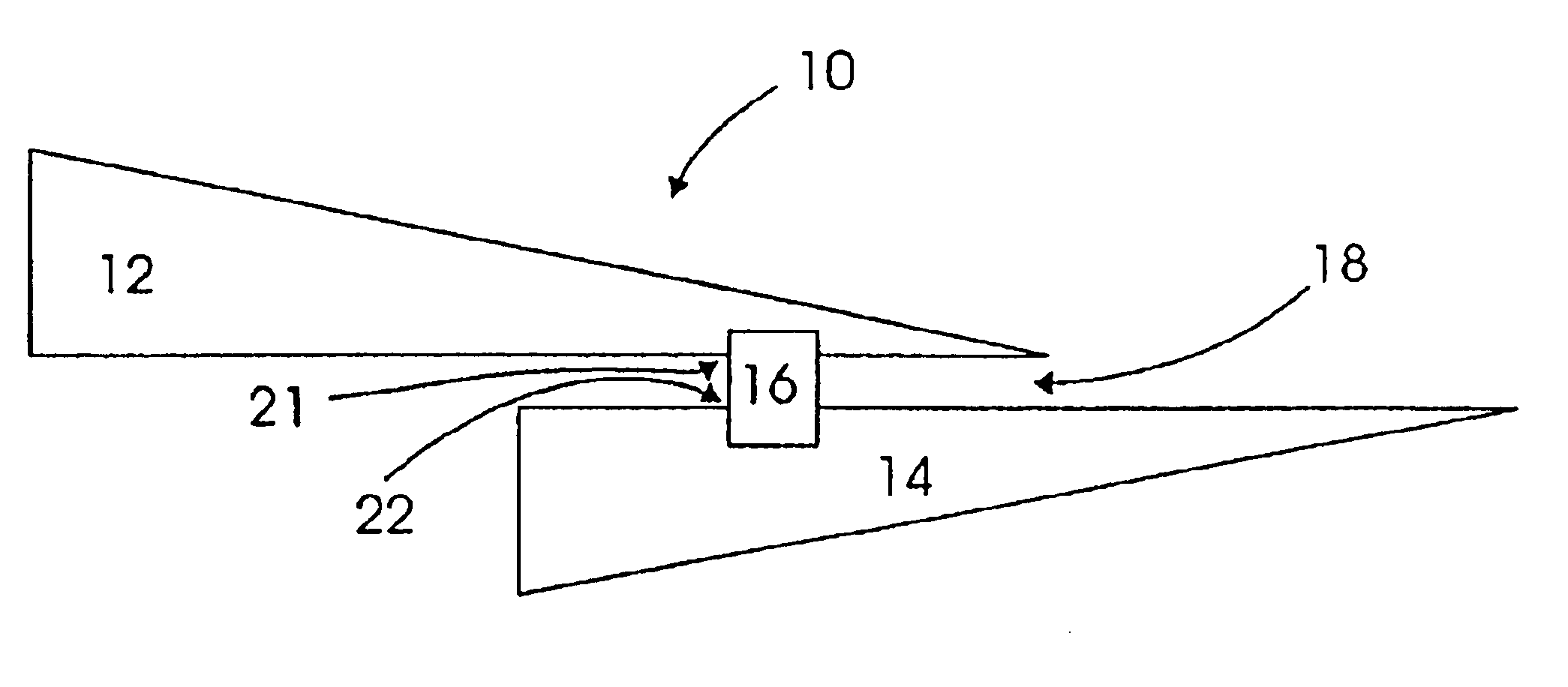
[0037]The present invention is directed to a radio frequency identification device (RFID) and its antenna system as it is attached to a package or container to communicate information about the package or container to an external reader. The package may be an individual package containing specific, known contents, or an individual, exterior package containing within it a group of additional, interior individual packages. The word “package” and “container” are used interchangeably herein to describe a material that houses contents, such as goods or other individual packages, and equivalent structures. The present invention should not be limited to any particular meaning or method when either “package” or “container” is used.

[0038]FIG. 1 illustrates one embodiment of the present invention that is found in an RFID tag 10 that includes a wireless communication device 16. The device 16 may be either active in generating itself the radio frequency energy in response to a received command,...


PUM


Abstract

An antenna system that is insensitive to the surface on which it is mounted for use with a RFID tag having a wireless communication device, including a plurality of conductive tabs coupled to the wireless communication device for receiving and radiating radio frequency energy. At least two of the tabs are substantially identical in shape and coupled to the wireless communication device at feedpoint differing in location on each of the two tabs wherein the width of said at least two of said plurality of tabs taken transverse to the longitudinal centerline axis of each tab varies with distance along the longitudinal centerline axis of each of said tabs from its feedpoint. Alternatively, the wireless communication device is coupled to the tab at a feedpoint selected at a location differing on each of the tabs where the conducting area per unit length of the longitudinal centerline axis of each tab varies with distance along the longitudinal centerline axis of each of said tabs from its feedpoint. A radio frequency reflecting structure is coupled to the conductive tabs for reflecting radio frequency energy radiated therefrom. A dielectric material is located intermediate the conductive tabs and the radio frequency reflecting means.

Description

BACKGROUND OF THE INVENTIONField of the Invention[0001]This invention relates to the field of Radio Frequency Identification (RFID) tags and labels, and in particular to tags and labels that include a surface insensitive antenna structure. This application incorporates by reference U.S. Pat. No. 6,451,154 entitled “RFID Manufacturing Concepts,” and U.S. patent application Ser. No. 10 / 323,490, entitled RFID LABEL AND METHOD OF MANUFACTURE.[0002]Current inventory and manufacturing methods rely on the ability to track and identify items of concern, such as inventory items, packages, individual parts, etc., and to communicate information concerning such items of concern in a wireless manner for processing and use. One known method of tracking and providing information on such items of concern is to attach to such item a wireless communication device, such as an active or passive transponder, incorporated into an identification tag or label that responds to radio frequency interrogation ...

Claims


Application Information

Patent Timeline
Patent Type & Authority Patents(United States)
IPC IPC(8): G06K19/077H01Q9/04H01Q23/00H01Q1/24H01Q1/22H01Q1/38H01Q5/10H01Q9/28H01Q9/40H01Q13/20
CPCG06K19/07749G06K19/07771G06K19/07786H01Q1/22H01Q1/2225H01Q1/38H01Q9/0407H01Q9/285H01Q9/40H01Q13/20H01Q23/00
Inventor FORSTER, IAN J.
Owner AVERY DENNISON CORP
Why Eureka
Try Eureka