
Reverse conducting IGBT driving method based on three-level diode desaturation control

A driving method and reverse conduction technology, applied in the direction of electrical components, output power conversion devices, etc., can solve the problems of static and dynamic loss of diodes, slow recognition speed, and insufficient accuracy, and achieve static loss and dynamic loss. Solve the effect of insufficient desaturation, high-speed and accurate detection

Active Publication Date: 2019-06-18
HUNAN UNIV
View PDF5 Cites 0 Cited by
  • Summary
  • Abstract
  • Description
  • Claims
  • Application Information

AI Technical Summary

Problems solved by technology

[0004] In order to overcome the inconsistencies between the static and dynamic losses of diodes that cannot be solved by two-level driving in the prior art, and the shortcomings of slow identification speed and insufficient precision of the working state of the reverse conduction IGBT, the present invention provides a three-level diode back-off Saturation control reverse conduction IGBT driving method, first use high-speed Hall sensor to quickly and accurately detect the load current, and judge the working mode of reverse conduction IGBT in real time, the recognition speed and accuracy are significantly improved

Method used


Image

  • Reverse conducting IGBT driving method based on three-level diode desaturation control
  • Reverse conducting IGBT driving method based on three-level diode desaturation control
  • Reverse conducting IGBT driving method based on three-level diode desaturation control

Examples


Embodiment Construction

[0024] Taking the upper tube driving the bridge arm of the reverse conducting IGBT as an example, the present invention will be further described in detail below in conjunction with the accompanying drawings.

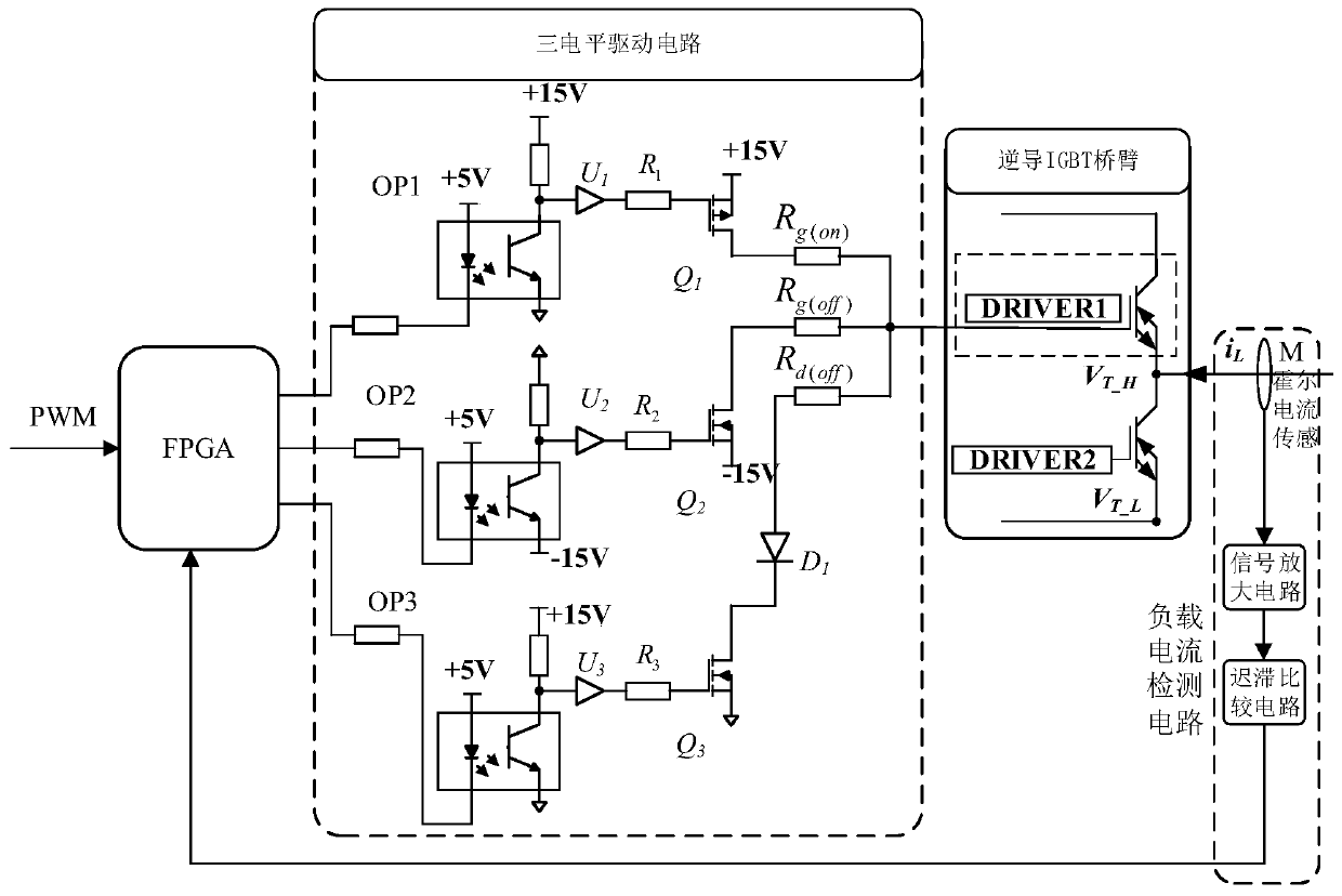
[0025] figure 1 It is the drive circuit for the three-level diode desaturation control in the embodiment of the present invention, mainly including, input PWM signal interface, FPGA logic circuit, load current detection circuit, three-level drive circuit, reverse conduction IGBT bridge arm; Said input PWM The signal interface is connected to the FPGA logic circuit; the FPGA logic circuit is connected to the input end of the three-level drive circuit; the output end of the three-level drive circuit is connected to the gate of the upper tube of the reverse-conducting IGBT bridge arm; The input terminal of the load current detection circuit is connected with the midpoint M of the reverse conducting IGBT bridge arm; the output terminal of the load current detection circuit...


PUM


Abstract

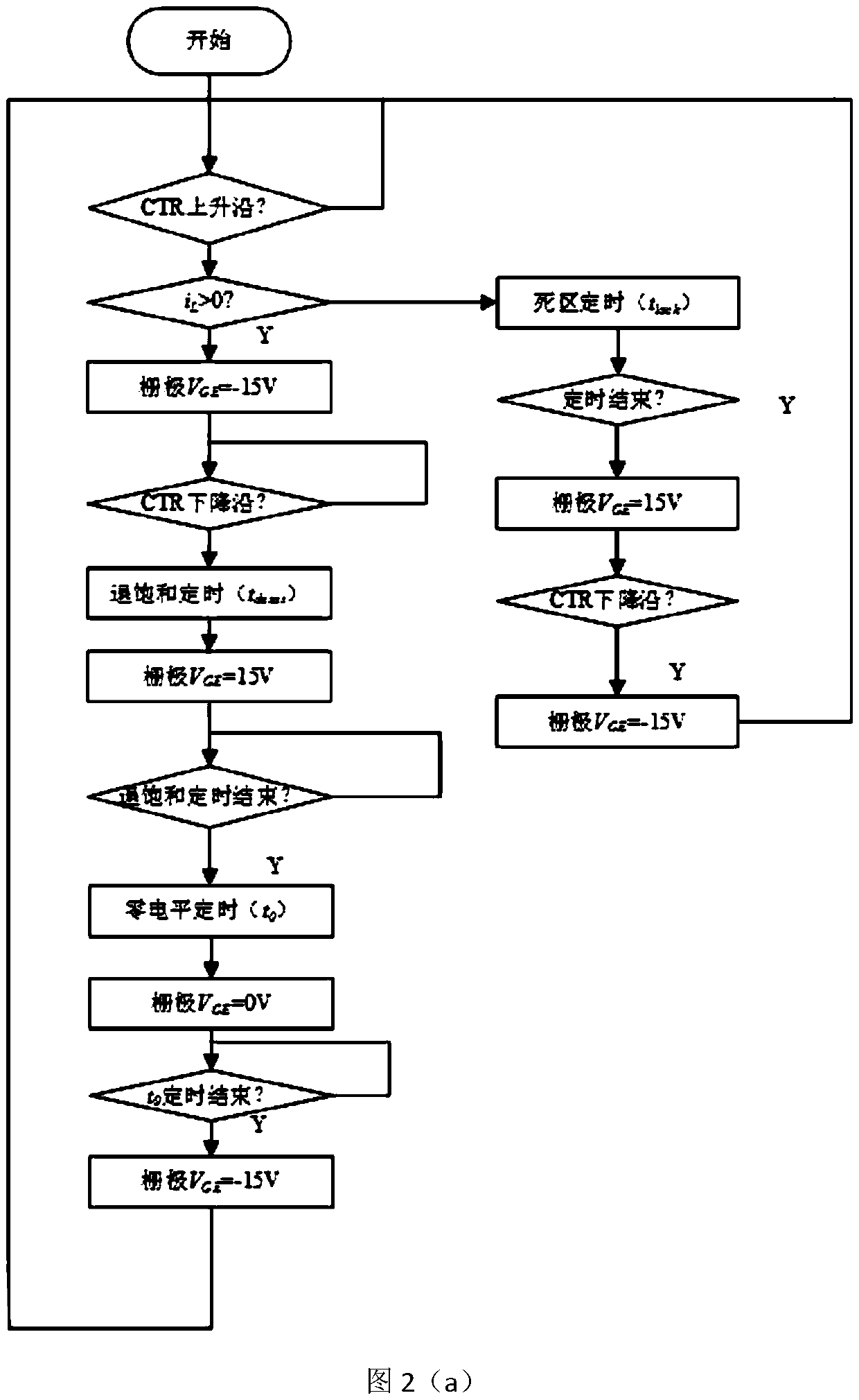
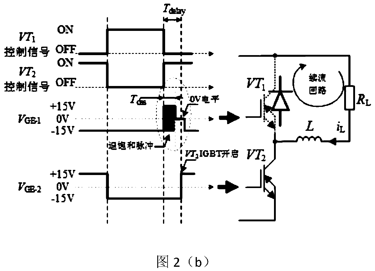
The invention provides a reverse conducting IGBT driving method based on three-level diode desaturation control. Firstly, a load current is detected through a high-speed Hall sensor circuit, so that aworking mode of a reverse conducting IGBT is judged. Secondly, for a diode mode, an FPGA is used to generate three-level control logic of -15V, 15V and 0V, and the three-level control logic is converted into a grid voltage through a designed driving circuit to drive the reverse conducting IGBT; and traditional two-level drive is adopted for a dead zone and an IGBT mode. According to the method, the speed and accuracy of judging the working mode of the reverse conducting IGBT are relatively high, and the hardware cost is low. The method can solve the mutual contradiction between the conductionloss and the dynamic loss of a diode, so that the switching loss of the reverse conducting IGBT is more effectively reduced, and the drive safety is improved.

Description

technical field [0001] The invention relates to a reverse conduction IGBT drive technology, in particular to a reverse conduction IGBT drive method for three-level diode desaturation control. Background technique [0002] In recent years, IGBT has gradually replaced thyristors due to its excellent comprehensive performance, and is widely used in many occasions: electric vehicles, light rail and other traction systems, power systems, home appliances and militarized weapons, etc. The performance requirements of high power density, high voltage and strong flow capacity have been driving the innovation of IGBT, and various new IGBTs emerge in endlessly. Among them, the reverse-conducting IGBT has once become a research hotspot in the world because of its small structure size, high power density, low cost, small parasitic parameters, and high reliability. [0003] There are obvious differences with the structure of ordinary IGBT. The collector of the cell structure of the revers...

Claims


Application Information

Patent Timeline
Patent Type & Authority Applications(China)
IPC IPC(8): H02M1/08
Inventor 陈燕东郭健周乐明姜捷刘傲阳王翔宇熊昊哲
Owner HUNAN UNIV
Learn More