
A Spinning Forming Method of Deep Conical Thin-wall Rotary Part with Flange

A technology of spinning forming and thin-wall rotation, which is applied in the field of spinning forming of deep conical thin-walled rotary parts with flanges, can solve the problems of fast hardening speed, uneven forming force of parts, and high tensile strength. Solve the effect of faster hardening speed, ensure wall thickness uniformity, and improve forming accuracy

Active Publication Date: 2020-06-09
NINGBO UNIV
View PDF1 Cites 0 Cited by
  • Summary
  • Abstract
  • Description
  • Claims
  • Application Information

AI Technical Summary

Problems solved by technology

[0004] The purpose of the present invention is to overcome the problems of fast hardening speed and high tensile strength of alloy materials in spinning forming in the prior art, and the linear speed difference of spinning wheels at different positions is huge, which easily causes the forming of parts to be affected. Insufficient of uneven force and uneven wall thickness, provide a spinning forming method for deep conical thin-walled rotary parts with flange, design multi-pass spinning forming, make spinning forming technology suitable for alloy materials, and design Different rotation speeds of the mandrel are used to ensure the uniformity of the wall thickness of the parts.

Method used


Image

  • A Spinning Forming Method of Deep Conical Thin-wall Rotary Part with Flange
  • A Spinning Forming Method of Deep Conical Thin-wall Rotary Part with Flange
  • A Spinning Forming Method of Deep Conical Thin-wall Rotary Part with Flange

Examples


Embodiment Construction

[0023] The present invention will be further described below in conjunction with the accompanying drawings and specific embodiments.

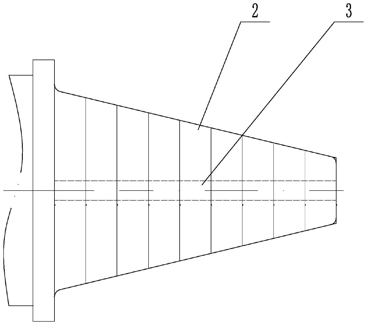
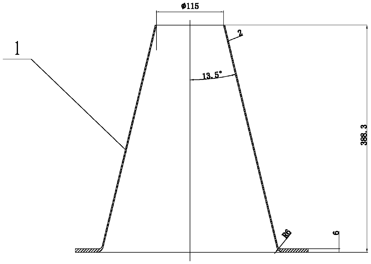
[0024] Such as Figure 1 to Figure 6 As shown in , the material of part 1 in this embodiment is superalloy GH3030, and the size is as figure 2 As shown, a spinning forming method of a deep conical thin-walled rotary part with a flange is described, the details are as follows:

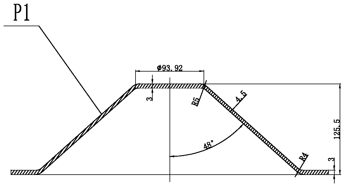
[0025] Determine the spinning pass. In this embodiment, 4 passes are taken, and the blank P is formed by spinning according to the fourth pass. 4 The volume, turning allowance, and spinning forming allowance, combined with the principle of equal volume, calculate the size of the circular flat blank, specifically, the part volume V p =602576mm 3 , the theoretical volume V of the circular slab blank p理 Equal to the volume V of the blank in the fourth pass P4 , V P4 =756373mm 3 , thus the theoretical diameter D of the circular flat blank can be obtained 理 ≈400mm. I...


PUM


Abstract

The invention relates to the technical field of spinning pressing forming, in particular to a spinning pressing forming method of a deep conical thin-walled rotary part with a flange. The method comprises the following steps of determining the number of times of spinning pressing, and working out the sizes of a circular flat plate blank according to the volume, turning allowance and spinning pressing forming allowance of the blank which is already subjected to the last time of spinning pressing forming and the equal volume principle; determining the process parameters of a spinning wheel and multi-section core dies during each time of spinning pressing according to the wall thickness and half taper angle of the blank during each time of spinning pressing forming, wherein the rotating speeds of the core dies are sequentially reduced from the small-diameter end of the core dies to the large-diameter end of the core dies; carrying out spinning pressing on the corresponding core dies withthe number of times of spinning pressing starting from 1 to n to gradually reduce the wall thickness or half taper angle of the blank until the blank formed after the last time of spinning pressing forming is obtained; and carrying out turning on the blank which is formed after the last time of spinning pressing forming. The spinning pressing forming method of the deep conical thin-walled rotary part with the flange is suitable for alloy materials, and the sectional and different rotating speeds of the core die are designed to ensure the wall thickness forming uniformity of the part.

Description

technical field [0001] The invention relates to the technical field of spinning forming, in particular to a spinning forming method of a deep conical thin-walled rotary part with a flange. Background technique [0002] A part with a flanged deep conical thin-walled rotary part, which is composed of a conical part and a flanged part welded. During the welding process, the deformation of the welding place is large, the dimensional accuracy of the parts cannot meet the requirements, and the process of shaping the parts after welding is more complicated and the effect is poor. In order to avoid the deformation caused by welding, most of the parts are now used. The overall spinning forming process guarantees the dimensional requirements of the parts, but some alloy materials have the problems of fast hardening speed and high tensile strength during spinning, and the deep taper of the parts leads to a large difference in diameter at different taper positions. Large, if the same c...

Claims


Application Information

Patent Timeline
Patent Type & Authority Patents(China)
IPC IPC(8): B21D22/16
Inventor 束学道李子轩王雨张松彭文飞朱颖岑泽伟
Owner NINGBO UNIV
Learn More