Raw material cutting device for machining and operation method thereof

A technology of mechanical processing and cutting equipment, which is applied in the direction of metal processing equipment, metal processing, metal processing machinery parts, etc., and can solve problems such as affecting the normal operation of the equipment, generating a large amount of waste, shortening the service life of the equipment, etc.

Inactive Publication Date: 2019-06-21
温州兴南环保科技有限公司
View PDF13 Cites 7 Cited by
  • Summary
  • Abstract
  • Description
  • Claims
  • Application Information

AI Technical Summary

Problems solved by technology

[0004] Based on the technical problems existing in the background technology, the present invention proposes a raw material cutting equipment for mechanical processing and its operation method, which has the characteristics of automatically cleaning waste chips during the cutting process, and solves the problem that the existing technology will generate a large amount of waste during cutting. waste, and the waste will affect the normal operation of the equipment, leading to the problem of shortening the service life of the equipment

Method used


Image

  • Raw material cutting device for machining and operation method thereof
  • Raw material cutting device for machining and operation method thereof
  • Raw material cutting device for machining and operation method thereof

Examples


Embodiment 1

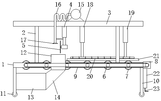
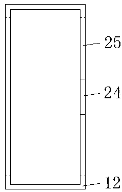
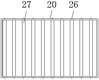
[0036] A raw material cutting equipment for mechanical processing, comprising a frame 1, the top of the frame 1 is connected to a top plate 3 through a pillar 2, the bottom of the top plate 3 is connected to a cutting machine 5 through a first cylinder 4, and the surface of the frame 1 is passed through a first The rotating shaft 6 is connected with the first transmission roller 7 in rotation, the side of the frame 1 is equipped with a brake motor 8, the output shaft of the brake motor 8 drives the first rotating shaft 6 to rotate through the transmission belt 9, the top of the frame 1 corresponds to the position of the cutting machine 5 A splash guard 12 is installed, and the bottom of the splash guard 12 communicates with a collection box 13 through a communication pipe 14 .

[0037] This technical solution automatically conveys and fixes the raw material 21, and cuts the raw material 21 by the cutting machine 5, and restricts the waste chips through the splash guard 12 after...

Embodiment 2

[0039] A raw material cutting equipment for mechanical processing, comprising a frame 1, the top of the frame 1 is connected to a top plate 3 through a pillar 2, the bottom of the top plate 3 is connected to a cutting machine 5 through a first cylinder 4, and the surface of the frame 1 is passed through a first The rotating shaft 6 is connected with the first transmission roller 7 in rotation, the side of the frame 1 is equipped with a brake motor 8, the output shaft of the brake motor 8 drives the first rotating shaft 6 to rotate through the transmission belt 9, the top of the frame 1 corresponds to the position of the cutting machine 5 A splash guard 12 is installed, the bottom of the splash guard 12 communicates with a collection box 13 through a connecting pipe 14, the bottom of the frame 1 is welded with a support leg 10, and the bottom of the support leg 10 is rotatably connected with a pulley 11, and the collection box 13 is installed on The surface of the leg 10.

[00...

Embodiment 3

[0042]A raw material cutting equipment for mechanical processing, comprising a frame 1, the top of the frame 1 is connected to a top plate 3 through a pillar 2, the bottom of the top plate 3 is connected to a cutting machine 5 through a first cylinder 4, and the surface of the frame 1 is passed through a first The rotating shaft 6 is connected with the first transmission roller 7 in rotation, the side of the frame 1 is equipped with a brake motor 8, the output shaft of the brake motor 8 drives the first rotating shaft 6 to rotate through the transmission belt 9, the top of the frame 1 corresponds to the position of the cutting machine 5 A splash guard 12 is installed, the bottom of the splash guard 12 communicates with a collection box 13 through a connecting pipe 14, the bottom of the frame 1 is welded with a support leg 10, and the bottom of the support leg 10 is rotatably connected with a pulley 11, and the collection box 13 is installed on The surface of supporting leg 10, ...


PUM


Abstract

The invention discloses a raw material cutting device for machining and an operation method of the raw material cutting device for machining. The raw material cutting device for machining comprises amachine frame. The top of the machine frame is connected with a top plate through support columns. The bottom of the top plate is connected with a cutting machine through a first air cylinder. The surface of the machine frame is rotationally connected with a first transmission roller through a first rotating shaft. A brake motor is installed on the side face of the machine frame. An output shaft of the brake motor drives the first rotating shaft to rotate through a transmission belt. The top of the machine frame is provided with an anti-splashing plate corresponding to the cutting machine in position. According to the raw material cutting device for machining and the operation method of the raw material cutting device for machining, the raw materials are automatically conveyed and fixed, the raw materials are cut through the cutting machine, after cutting, the anti-splashing plate limits waste chips, the rebounding waste chips are blown into a collection box through an air blower, thewaste chips in the collection box can also be cleared, and in this way the problems that in the prior art, during cutting, a large number of waste chips can be generated, the waste chips can influencenormal operation of the equipment, and the service life of the equipment is shortened as a result are solved.

Description

technical field [0001] The invention relates to the technical field of mechanical processing, in particular to a raw material cutting device for mechanical processing and an operation method thereof. Background technique [0002] Machinery refers to the general term for machines and mechanisms. Machinery is a tool device that can help people reduce the difficulty of work or save labor. Items such as chopsticks, brooms, and tweezers can all be called machines, and they are simple machines. A complex machine is composed of two or more simple machines. These more complex machines are usually called machines. From the point of view of structure and motion, there is no difference between a mechanism and a machine, and it is generally called a machine. [0003] Machining refers to the process of changing the shape or performance of a workpiece through a mechanical device. According to the difference in processing method, it can be divided into cutting processing and pressure p...

Claims


Application Information

Patent Timeline
Patent Type & Authority Applications(China)
IPC IPC(8): B23Q11/08B23Q11/00B23Q7/05B23Q3/08
Inventor 不公告发明人
Owner 温州兴南环保科技有限公司
Why Eureka
Try Eureka