Hydraulically-driven hydrogen compressor

A compressor and hydrogen technology, applied in the field of compressors, can solve problems such as shortened service life and insufficient stability of hydrogen output pressure, and achieve the effects of shortened service life, stable hydrogen output pressure, and improved compression capacity

Pending Publication Date: 2022-07-26
上海氢枫能源技术有限公司
View PDF0 Cites 0 Cited by
  • Summary
  • Abstract
  • Description
  • Claims
  • Application Information

AI Technical Summary

Problems solved by technology

[0004] The invention aims to solve the technical problems that the service life of the existing electric-driven hydrogen compressor is shortened due to frequent start and stop, and the hydrogen output pressure is not stable enough

Method used


Image

  • Hydraulically-driven hydrogen compressor
  • Hydraulically-driven hydrogen compressor

Examples


Embodiment Construction

[0023] The preferred embodiments of the present invention are specifically described below with reference to the accompanying drawings, wherein the accompanying drawings constitute a part of the present application, and together with the embodiments of the present invention, are used to explain the principles of the present invention, but are not used to limit the scope of the present invention.

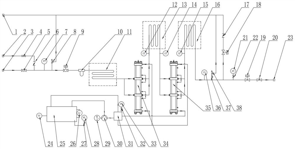
[0024] Please refer to figure 1 , an embodiment of the present invention provides a hydraulically driven hydrogen compressor, including: a gas circuit and an oil circuit;

[0025] The gas circuit includes a low-pressure hydrogen pipe port 3, a hydrogen pipe ball valve 5, an air intake pipe pneumatic valve 9, a pre-compression cooler 11, a primary piston compression cylinder 34, a primary cooling assembly 13, and a secondary piston. The compression cylinder 35, the secondary cooling assembly 16, the pneumatic valve 19 of the exhaust pipeline and the exhaust pipe port 23; wherein, the ...


PUM


Abstract

The invention provides a hydraulically-driven hydrogen compressor, and relates to the field of compressors. The hydraulically-driven hydrogen compressor comprises a gas path and an oil path. The low-pressure hydrogen pipeline comprises a low-pressure hydrogen pipe orifice, a hydrogen pipeline ball valve, an air inlet pipeline pneumatic valve, a pre-compression cooler, a first-stage piston compression cylinder body, a first-stage cooling assembly, a second-stage piston compression cylinder body, a second-stage cooling assembly, an exhaust pipeline pneumatic valve and an exhaust pipe orifice which are sequentially connected in series; the oil way comprises an oil tank, a motor, an electric pump set and a three-valve set. The motor is connected with the electric pump set; an oil inlet of the electric pump set is communicated with the oil tank, and an oil outlet of the electric pump set is communicated with oil inlets of the first-stage piston compression cylinder body and the second-stage piston compression cylinder body through the three-valve set. Oil outlets of the first-stage piston compression cylinder body and the second-stage piston compression cylinder body are respectively communicated with an oil tank through a three-valve group; the technical problem that the service life of an existing electrically-driven hydrogen compressor is shortened due to frequent starting and stopping can be solved, and the hydrogen output pressure is stable.

Description

technical field [0001] The invention relates to the field of compressors, in particular to a hydraulically driven hydrogen compressor. Background technique [0002] Nowadays, compressors are the key equipment for hydrogen boosting in hydrogenation stations, and the reliability of their equipment performance directly determines the overall operational reliability of hydrogenation stations. At present, traditional diaphragm compressors are mostly used in hydrogenation stations. [0003] The diaphragm compressor in the hydrogen refueling station is selected according to the design conditions such as the daily hydrogen refueling capacity of the hydrogen refueling station, the number of vehicles, and the filling amount of a single vehicle. Therefore, during the period of fluctuating hydrogen use, the electric drive compressor Frequent start and stop are required to adjust the output power, and frequent start and stop will greatly affect the service life of the electric drive comp...

Claims


Application Information

Patent Timeline
Patent Type & Authority Applications(China)
IPC IPC(8): F04B35/02F04B25/00F04B39/06F04B39/16
CPCF04B35/008F04B25/005F04B39/06F04B39/16
Inventor 方沛军宣锋王志成姜方伍远安曹俊
Owner 上海氢枫能源技术有限公司
Why Eureka
Try Eureka