
Laterally formed oil cylinder slider mechanism

A slider and oil cylinder technology, applied in the field of oil cylinder slider mechanism, can solve the problems of difficult mold manufacturing, increased mold manufacturing cost, large mold size, etc., and achieve stable and reliable demoulding, easy processing and manufacturing, and simple structure.

Pending Publication Date: 2019-06-21
PERLMAN ELECTRICAL KUSN
View PDF0 Cites 0 Cited by
  • Summary
  • Abstract
  • Description
  • Claims
  • Application Information

AI Technical Summary

Problems solved by technology

If there is a long groove feature on the side of the buckle, because the slider and the groove feature will interfere and conflict, the traditional mold will make the size of the mold very large and the structure complex, which will bring more difficulties to the production of the mold. Many difficulties increase the manufacturing cost of the mold

Method used


Image

  • Laterally formed oil cylinder slider mechanism
  • Laterally formed oil cylinder slider mechanism

Examples


Embodiment Construction

[0015] The concept, specific structure and technical effects of the present invention will be further described below in conjunction with the accompanying drawings, so as to fully understand the purpose, characteristics and effects of the present invention.

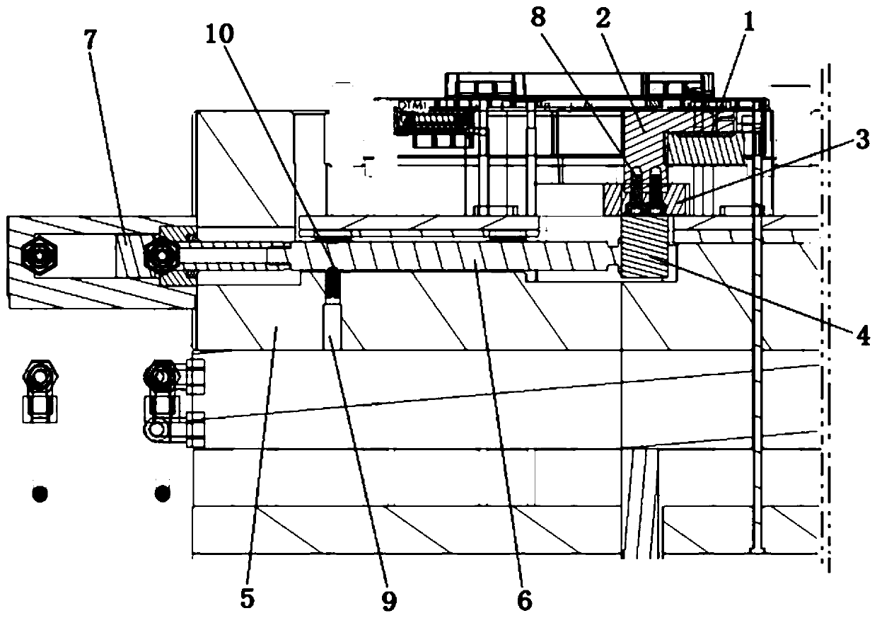
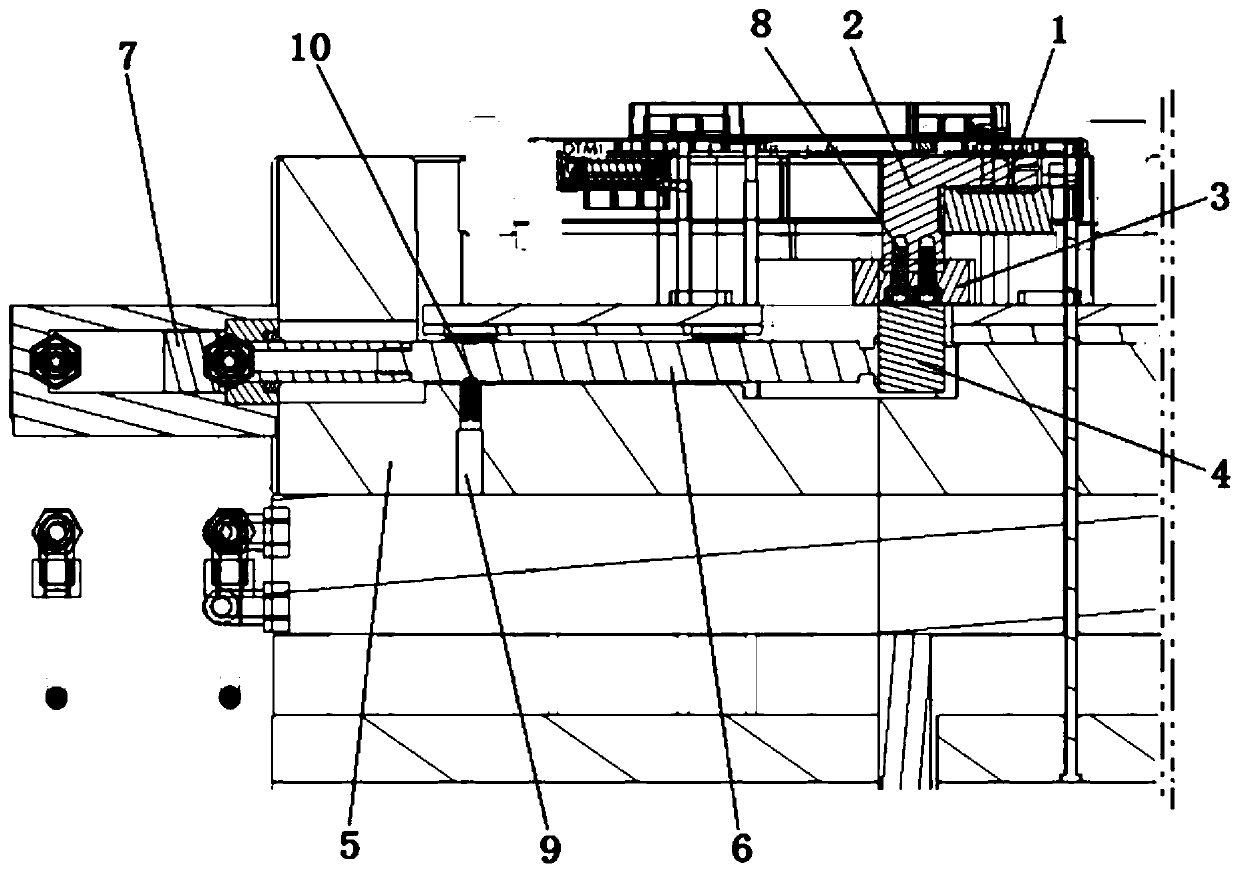
[0016] refer to figure 1 , the present invention includes a slider insert 2 for forming a product snap groove structure 1, one end of the slider insert 2 is provided with a slider connection guide block 3, the slider connection guide block 3 is connected to the slider base 4, and the slider The base 4 is placed on the male template 5, the slider base 4 is provided with a dovetail groove, and the corresponding position of the male template 5 is provided with a slide rail.

[0017] The pull rod 6 is connected to the slider base 4 along the sliding direction of the slider insert 2 , and the other end of the pull rod 6 is connected to an oil cylinder 7 , and the oil cylinder 7 is fixed to the outside of the male template 5 . ...


PUM


Abstract

The invention discloses a laterally formed oil cylinder slider mechanism. The laterally formed oil cylinder slider mechanism comprises a pull rod and a slider casting insert, a slider connection guideblock is arranged at one end of the slider casting insert, the sliderconnection guide block is connected with a slider base, and the slider casting insert, the slider connection guide block, and theslider base are integrally connected through a screw; the slider base is mounted on a sliding track of a public template, and a spring dial bead is arranged on the public template; and the pull rod isconnected with the slider base in the sliding direction of the slider casting insert, the other end of the pull rod is connected with an oil cylinder, and the pull rod is provided with a positioninggroove matched with the spring dial bead. The laterally formed oil cylinder slider mechanism drives the slider casting insert to move in a balanced mode to avoid the buckle groove structure of a product through extraction power of the oil cylinder, the structure is simple, demolding is stable and reliable, manufacturing is easy, and the mold manufacturing cost can be reduced greatly.

Description

technical field [0001] The invention relates to the technical field of plastic molds, in particular to a laterally formed oil cylinder slider mechanism. Background technique [0002] According to the requirements of product functions, it is often necessary to design a barb-type buckle design on the mother mold side (gluing side), and the mold needs to be designed with slider core pulling in two directions to complete. If there is a long groove feature on the snap edge, because the slider and the groove feature will interfere and conflict, the traditional mold will make the size of the mold very large and the structure is complex, which brings more difficulties to the production of the mold. Many difficulties increase the manufacturing cost of the mold. SUMMARY OF THE INVENTION [0003] In view of the above-mentioned defects of the prior art, the technical purpose of the present invention is to provide a laterally formed hydraulic cylinder slider mechanism with simple stru...

Claims


Application Information

Patent Timeline
Patent Type & Authority Applications(China)
IPC IPC(8): B29C45/33B29C45/44
Inventor 周军
Owner PERLMAN ELECTRICAL KUSN
Learn More