Dead zone image acquiring method and terminal device

A terminal equipment, blind spot technology, applied in optical observation devices, transportation and packaging, vehicle components, etc., to improve driving or reversing safety, eliminate blind spots, and improve driving safety.

Inactive Publication Date: 2019-06-21
北京七鑫易维科技有限公司 +1
View PDF10 Cites 7 Cited by
  • Summary
  • Abstract
  • Description
  • Claims
  • Application Information

AI Technical Summary

Problems solved by technology

[0003] However, whether it is a 360-degree panoramic image or a reversing radar, the acquired reversing images all form blind spots due to the existence of the A, B and C pillars of the car.

Method used


Image

  • Dead zone image acquiring method and terminal device
  • Dead zone image acquiring method and terminal device
  • Dead zone image acquiring method and terminal device

Examples


Embodiment Construction

[0063] This application provides a method for acquiring a blind spot picture and a terminal device, which are used to determine the blind spot of the driver in the cab by collecting the characteristics of the driver's head, and display the blind spot picture, so as to reduce the driving blind spot and improve driving safety .

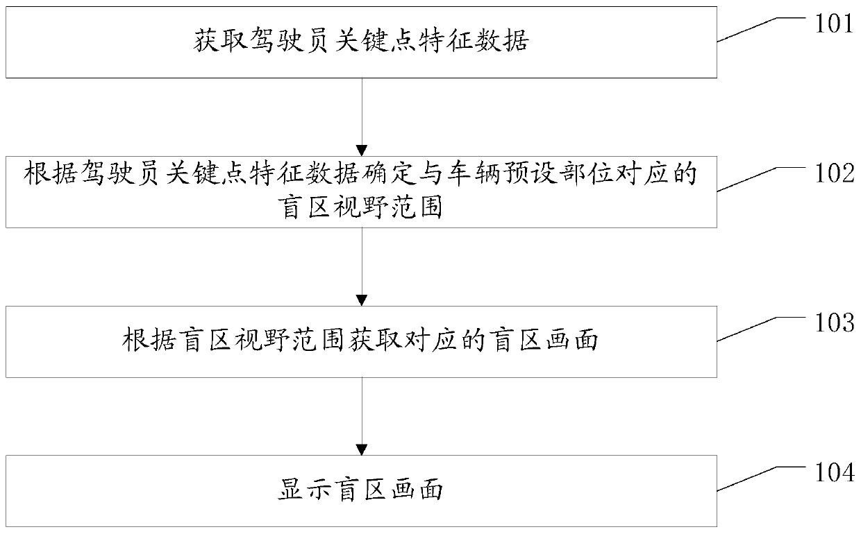
[0064] When the vehicle is running, the A-pillar, B-pillar, and C-pillar inside the vehicle will affect the driver's vision when driving the vehicle. Lead to blind spots in the cab, affecting driving safety. In the embodiment of the present application, the driver's key point feature data can be combined to determine the driver's blind spot and display the blind spot picture to improve driving safety. Specifically, see figure 1 , a schematic flowchart of a method for acquiring a blind spot picture provided in an embodiment of the present application may include:

[0065] 101. Obtain the key point feature data of the driver;

[0066] In the embodimen...


PUM


Abstract

The invention provides a dead zone image acquiring method and a terminal device, which are used for determining a dead zone of a driver in a cab by gathering head features of the driver, and displaying an image of the dead zone, so as to reduce the driving dead zone and improve the driving safety. The method comprises: acquiring key point feature data of the driver; determining a dead zone visionrange corresponding to a preset position of a vehicle according to the key point feature data of the driver; acquiring a dead zone image corresponding to the dead zone vision range; and displaying thedead zone image.

Description

technical field [0001] The present application relates to the field of automobiles, and in particular to a method for acquiring pictures in a blind spot and a terminal device. Background technique [0002] With the continuous upgrading of automobile companies, more and more high-tech configurations are constantly appearing on automobiles, such as reversing radar and 360-degree panoramic images. Specifically, for example, a 360-degree panoramic image can clearly display the environment around the vehicle body. The 360-degree panoramic image has 4 cameras on the front, rear, left, and right sides, which respectively collect images of the blind spots on the front side of the car and the rear of the car. After processing, a panoramic top view around the vehicle is finally formed and displayed on the display screen. location and surrounding environment. [0003] However, whether it is a 360-degree panoramic image or a reversing radar, the acquired reversing images all form blin...

Claims


Application Information

Patent Timeline
Patent Type & Authority Applications(China)
IPC IPC(8): B60R1/00
Inventor 黄通兵陈爽秦林婵
Owner 北京七鑫易维科技有限公司
Why Eureka
Try Eureka