
A cylindrical cathode device with magnetic shoe that can move in real time

A magnetic shoe and column type technology, which is applied in the field of magnetron sputtering coating equipment, can solve the problems that the control of columnar magnetron sputtering cathode and columnar arc ion plating magnetic shoe is difficult to achieve, and achieve air intake and sealing sexual effect

Active Publication Date: 2021-03-16
苏州艾钛科纳米科技有限公司
View PDF4 Cites 0 Cited by
  • Summary
  • Abstract
  • Description
  • Claims
  • Application Information

AI Technical Summary

Problems solved by technology

[0009] At this stage, it is difficult to realize the control of cylindrical magnetron sputtering cathode and cylindrical arc ion plating magnetic shoe

Method used


Image

  • A cylindrical cathode device with magnetic shoe that can move in real time
  • A cylindrical cathode device with magnetic shoe that can move in real time
  • A cylindrical cathode device with magnetic shoe that can move in real time

Examples


Embodiment 1

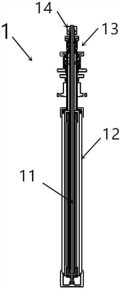
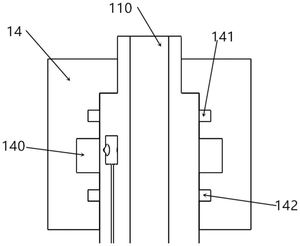
[0040] Such as Figure 2-Figure 10 As shown, a cylindrical cathode device with a magnetic shoe that can be moved in real time includes an air-push magnetic shoe 11, a target tube assembly 12, a target head assembly 13, and an air inlet sealing seat 14; wherein:

[0041]The air-push magnetic shoe 11 includes a water-air core 110, a rubber ring 111, an upper and lower threaded sleeve 115, a locking ring 112, an upper and lower gland 114, and a magnetic yoke 113; the rubber ring 111 is set on the water-air core 110, the upper and lower ends of the outer edge of the rubber ring 111 are bonded to the upper and lower threaded sleeves 115; the snap ring 112 and the yoke 113 are symmetrically bonded to the rubber ring 111; the upper and lower The gland 114 is assembled on the upper and lower threaded sleeves 115;

[0042] The target tube assembly 12 includes a shield cover, an insulating sleeve, a target tube 122, a target tube upper connecting tube 120 and a target tube upper and lo...

Embodiment 2

[0056] The main difference between Embodiment 2 and Embodiment 1 is that an external arc striking device with a rotating cylinder (common structure, not shown) is required, and the other parts are the same in structure and will not be repeated here.

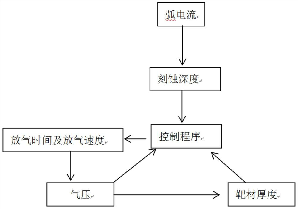
[0057] During the working process of air-push columnar rotary arc ion plating, in the initial state, the air pressure in the expansion chamber 03 is the largest, and the yoke 113 is attached to the upper and lower glands 114 by the air pressure, and then in the actual use process, it can be adjusted according to the type of target material. (Thickness), arc current calculation to obtain the etching speed and etching depth of the target, and set the deflation time and rate of the flow deflation valve, so as to realize the position of the magnetic shoe in the cathode during the discharge process of the arc ion plating target Changes in real time.

[0058] The invention is a new type of cylindrical cathode which can be moved by magn...


PUM


Abstract

The invention relates to a column type cathode device with a magnetic shoe capable of achieving real-time displacement. The column type cathode device comprises the air push type magnetic shoe, a target pipe assembly, a target head assembly and an air inlet sealing seat; the air push type magnetic shoe is internally provided with a water gas core where cooling water and compressed air can be led in, a rubber ring and a magnet yoke are pasted to the air push type magnetic shoe, an air inlet chamber is arranged between the water gas core and the inner side of bonding rubber, and the magnet yokeis pasted to the outer side of the rubber; the principle is that displacement of the magnet yoke is achieved through shaft surface displacement caused by changing of air pressure in the air inlet chamber between the rubber and the water gas core, and movement of the magnetic shoe in a column type cathode is achieved; and meanwhile, a control program is used for achieving the real-time automatic movement of the magnetic shoe according to the target use time. The column type cathode device can greatly improve the repeatability of the technology process, greatly improves the target utilization rate, is suitable for magnetron sputtering and arc ion plating of the cylindrical cathode, and can be applied to high precision and precious metal film deposition processes.

Description

technical field [0001] The invention belongs to the technical field of magnetron sputtering coating equipment, and relates to a cylindrical cathode device whose magnetic shoe can move in real time. Background technique [0002] Arc ion plating and magnetron sputtering in physical vapor deposition technology are widely used in vacuum coating industry. [0003] Magnetron sputtering coating is to install a magnet on the back side of the target in a vacuum chamber so that a closed magnetic field is generated on the surface of the target along the direction perpendicular to the electric field. The closed magnetic field interacts with the electric field to make the electrons close on the target surface. The magnetic field runs in a spiral shape. [0004] The main working principle of magnetron sputtering is that a glow discharge occurs between the electrode plates. During the discharge process, the electrons are affected by the magnetic field to produce a spiral motion, which inc...

Claims


Application Information

Patent Timeline
Patent Type & Authority Patents(China)
IPC IPC(8): C23C14/32C23C14/35
Inventor 郎文昌刘伟胡晓忠
Owner 苏州艾钛科纳米科技有限公司
Learn More