Immunomagnetic test paper and immunomagnetic measurement device

The technology of a measuring device and a detecting device is applied in the fields of immunomagnetic test strips and immunomagnetic measuring devices, which can solve the problems of undetectable and weak changes in electrical signals, and achieves the effect of convenient operation.

Active Publication Date: 2019-06-21
浙江佳米生物医药科技有限公司
View PDF6 Cites 0 Cited by
  • Summary
  • Abstract
  • Description
  • Claims
  • Application Information

AI Technical Summary

Problems solved by technology

[0002] In the experiment of immunomagnetic reaction, in order to check the positive reaction, it often needs to be implemented with the help of magnetoelectric conversion equipment. The existing experimental equipment often needs to combine the test paper with the magnetic The electric induction device is connected to form a corresponding circuit, and then the detection is carried out. However, in this way, the position of the magnetic induction device and the test paper is relatively fixed, and the electrical signal in the formed circuit changes weakly. Therefore, the test paper with weak immune magnetic response When testing, there are often situations that cannot be detected

Method used


Image

  • Immunomagnetic test paper and immunomagnetic measurement device
  • Immunomagnetic test paper and immunomagnetic measurement device
  • Immunomagnetic test paper and immunomagnetic measurement device

Examples


Embodiment 1

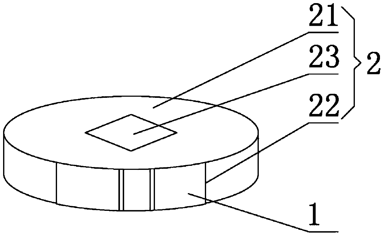
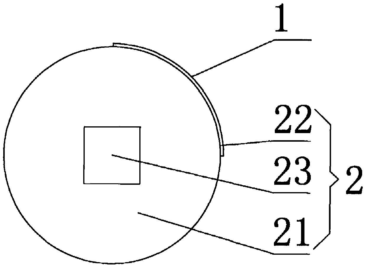
[0057] Such as figure 1 and figure 2 As shown, this embodiment discloses an immunomagnetic test paper. The immunomagnetic test paper includes a test paper body 1 and a carrier 2, and the test paper body 1 is fixed to the carrier 2. Wherein: the bottom plate of the test paper body 1 is sequentially pasted with sample pads, magnetic particle-labeled binding pads, chromatographic membranes and water-absorbent pads pre-coated with detection lines and quality control lines; the carrier 2 includes a fixed Connected loading body 21 and loading portion 22, the loading body 21 is provided with an assembly hole 23, the assembly hole 23 is used to cooperate with the rotating shaft, so as to realize the synchronous rotation of the loading body 21 and the rotating shaft The surface of the loading part 22 parallel to the rotation axis is the first side, the test paper body 1 is fixedly connected to the first side, and the detection line and the quality control line are parallel to the ro...

Embodiment 2

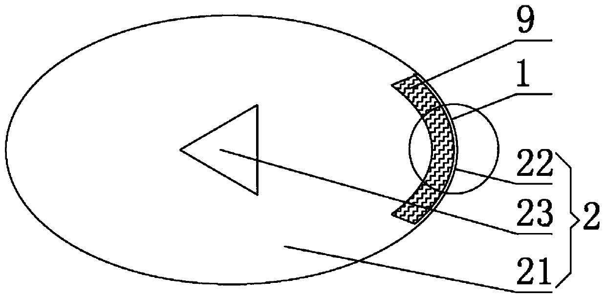
[0063] Such as Figure 3 to Figure 6 As shown, this embodiment provides an immunomagnetic test paper, which is different from the immunomagnetic test paper embodiment 1 in that: the loading body 21 is oval, the assembly hole is triangular, and the loading part 22 is arranged on The major axis of the ellipse. So that the distance between the test paper body 1 and the magnetoelectric induction device 4 is relatively close, thereby increasing the electrical signal in the magnetoelectric reaction.

[0064] Preferably, a buffer is provided between the test paper body 1 and the loading portion 22 to allow the test paper body 1 to elastically contact the magnetoelectric induction device 4 . Specifically, a groove is provided on the loading portion 22, and the buffer member 9 is arranged in the groove. In this embodiment, the buffer member 9 is a sponge.

[0065] In order to realize the reutilization of the loading body 21, the loading part 22 is detachably connected to the loading...

Embodiment 3

[0077] Such as Figure 7 As shown, this embodiment provides an immunomagnetic test paper, which is different from the immunomagnetic test paper embodiment 1 in that three test paper bodies 1 are provided on one carrier 2 . Through this embodiment, when one carrier 2 rotates, it can simultaneously drive three test paper bodies 1 to rotate.

[0078] In a specific implementation, the thickness of the object body 21 is between 1.5 cm and 15 cm. In the embodiment where the thickness of the loading body 21 is greater than 4 cm, since the width of each test paper body 1 is generally less than 2 cm, each loading body 21 may be provided with more than two test paper bodies 1 . That is to say, a plurality of test paper bodies 1 are provided on one said object body 21 .

[0079] As an alternative embodiment, two test paper bodies 1 may also be provided on one carrier 2 .

[0080] As an alternative embodiment, four, five, six, seven or eight test paper bodies 1 may also be provided on ...


PUM

PropertyMeasurementUnit
diameteraaaaaaaaaa
thicknessaaaaaaaaaa

Abstract

The invention relates to the field of an immunomagnetic test, and specifically relates to immunomagnetic test paper and an immunomagnetic measurement device. The test paper comprises an object loadingbody and a test paper body fixed thereon, the object loading body comprises an object carrying body and a loading portion that are fixedly connected, and the object carrying body is provided with anassembly hole used for cooperating with a rotating shaft. The measurement device includes the immunomagnetic test paper sleeving a first end of the rotating shaft; a motor is connected to a second endof the rotating shaft, and drives the rotating shaft to rotate; a magneto-electric induction device is disposed at a position opposite to the immunomagnetic test paper; an electrical signal detectingdevice is connected to the magneto-electric induction device; and when the immunomagnetic test paper rotates, both a detection line and a quality control line on the test paper body can cut a magnetic induction line generated by the magneto-electric induction device, the magneto-electric induction device generates an electrical signal, and the electrical signal detecting device can acquire the electrical signal. The immunomagnetic test paper and the immunomagnetic measurement device are simple in structure, are convenient to operate, and are sensitive in signal.

Description

technical field [0001] The invention relates to the field of immunomagnetic tests, in particular to an immunomagnetic test paper and an immunomagnetic measuring device. Background technique [0002] In the experiment of immunomagnetic reaction, in order to check the positive reaction, it often needs to be implemented with the help of magnetoelectric conversion equipment. The existing experimental equipment often needs to combine the test paper with the magnetic The electric induction device is connected to form a corresponding circuit, and then the detection is carried out. However, in this way, the position of the magnetic induction device and the test paper is relatively fixed, and the electrical signal in the formed circuit changes weakly. Therefore, the test paper with weak immune magnetic response When testing, there are often situations that cannot be detected. Contents of the invention [0003] In view of this, the present invention provides a novel immunomagnetic ...

Claims


Application Information

Patent Timeline
Patent Type & Authority Applications(China)
IPC IPC(8): G01N33/558
Inventor 杨叶民
Owner 浙江佳米生物医药科技有限公司
Why Eureka
Try Eureka