
Gearbox device of speed regulating tapping machine

A technology of gear boxes and drilling machines, which is applied in positioning devices, boring/drilling, drilling/drilling equipment, etc., which can solve the problem of poor sealing of drilling machines, unstable operation of equipment, and inconvenient operation and use and other problems, to achieve the effect of good fixing effect, convenient operation and simple on-site installation

Inactive Publication Date: 2019-06-25
安徽同发设备股份有限公司
View PDF7 Cites 4 Cited by
  • Summary
  • Abstract
  • Description
  • Claims
  • Application Information

AI Technical Summary

Problems solved by technology

[0004] Aiming at the deficiencies of the prior art, the present invention provides a gear box device for a speed-regulating hole drilling machine, which can prevent uneven stress when the pipe clamp is installed, and prevent the device from shaking during hole opening, so that the quality of the hole can be improved. , On-site installation is simple, easy to operate, safe and reliable, easy to work under the tunnel, can increase the service life of the drilling machine, and can realize drilling operations on various material pipelines, suitable for drilling various material pipelines on the market, and truly do Thanks to the advantages of one machine with multiple functions, it solves the problem that the same traditional drilling equipment cannot drill holes for different pipes. The drilling machine is large in size and inconvenient to work in the tunnel. It is easy to be damaged when working in the environment, and the speed cannot be adjusted according to the actual situation of the site. The operation is inconvenient, the work efficiency is low, the equipment is unstable, and it is difficult to meet the actual needs of production.

Method used


Image

  • Gearbox device of speed regulating tapping machine
  • Gearbox device of speed regulating tapping machine
  • Gearbox device of speed regulating tapping machine

Examples


Embodiment Construction

[0025] The following will clearly and completely describe the technical solutions in the embodiments of the present invention with reference to the accompanying drawings in the embodiments of the present invention. Obviously, the described embodiments are only some, not all, embodiments of the present invention. Based on the embodiments of the present invention, all other embodiments obtained by persons of ordinary skill in the art without making creative efforts belong to the protection scope of the present invention.

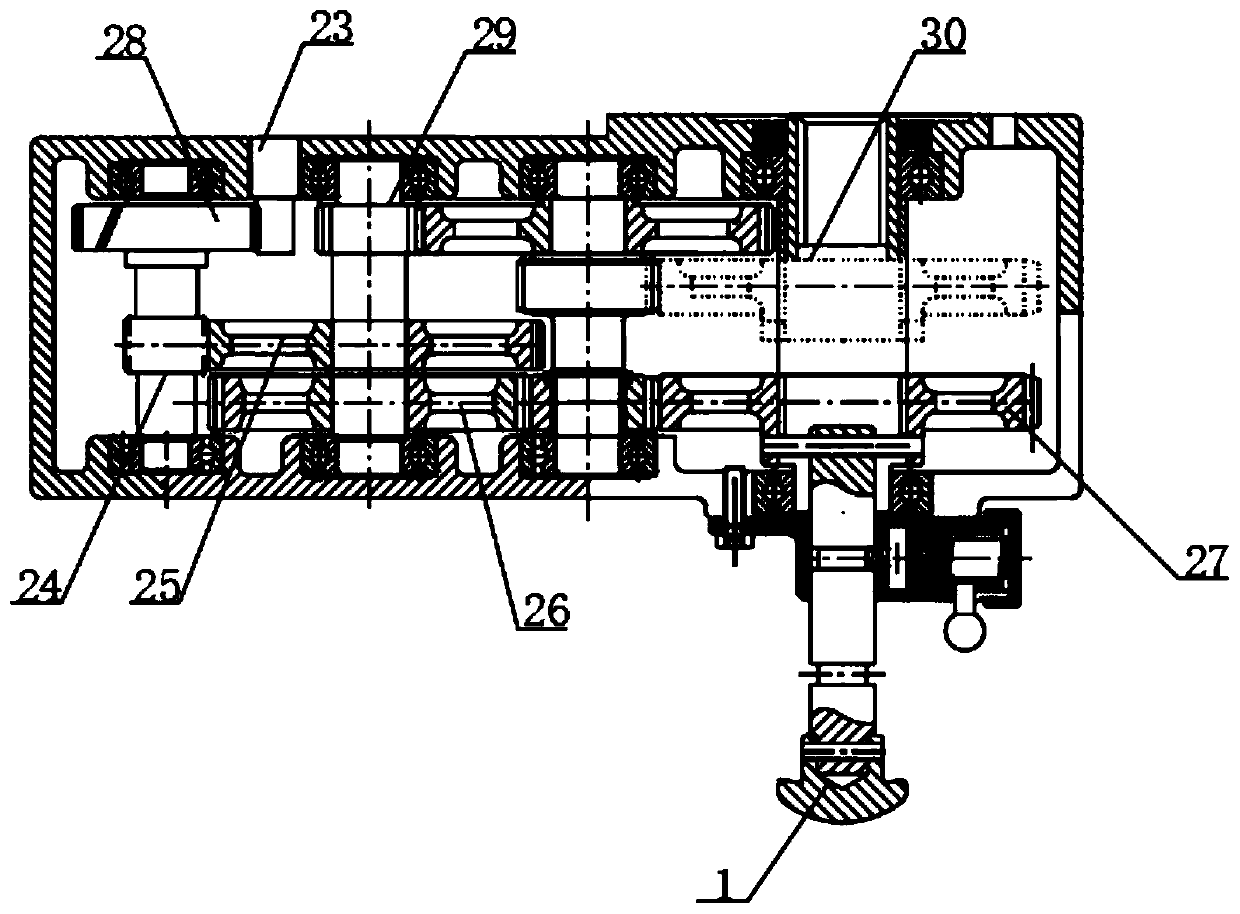
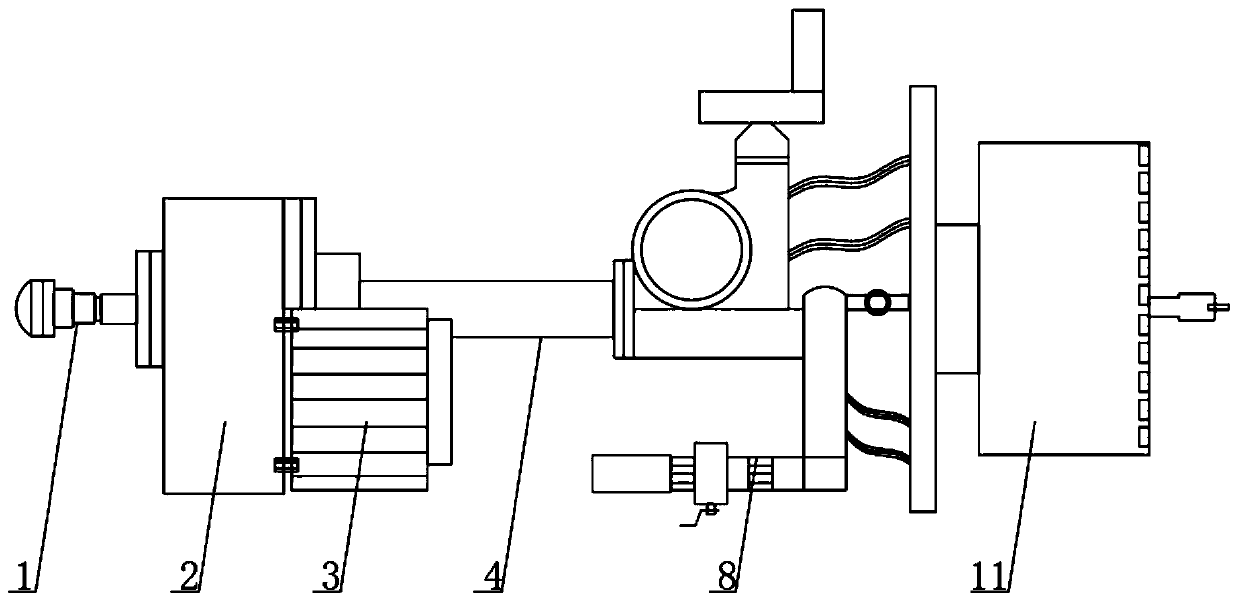
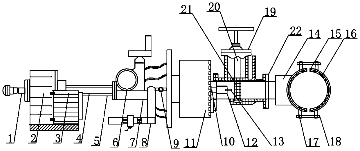
[0026] see Figure 1-3 , a gear box device for a speed-regulating drilling machine, comprising a pull rod 1, one end of the pull rod 1 is provided with a gear box main body 2, and the outer surface of one end of the gear box main body 2 is provided with a DC slotless brushless main motor 3, and the gear box main body One end of 2 is provided with a main shaft sleeve 4 close to the top of the DC slotless brushless main motor 3, the inner side of the main shaft ...


PUM


Abstract

The invention relates to the field of tapping machines and discloses a gearbox device of a speed regulating tapping machine. The gearbox device comprises a pull rod. A gearbox main body is arranged atone end of the pull rod, a direct current slotless and brushless main motor is arranged on the outer surface of one end of the gearbox main body, a main shaft sleeve is arranged on the outer surfaceof one end of the direct current slotless and brushless main motor, a spindle is arranged on the inner side of the main shaft sleeve on one end of the direct current slotless and brushless main motor,a body is arranged on the outer side of the main shaft sleeve on one end of the direct current slotless and brushless main motor, and a hand wheel is arranged at the upper end of the body. Accordingto the gearbox device of the speed regulating tapping machine, uneven stress when a pipe clamp is mounted is prevented, and the gearbox device is prevented from swinging during tapping, so that the tapping quality is better, and the gearbox device is simple in field installation, safe and reliable and convenient for operations under a underground tunnel. The service life of the tapping machine canbe prolonged, and the gearbox device can achieve tapping operations on pipelines of various materials, is suitable for tapping the pipelines of various materials in the current market, and is truly multipurpose.

Description

technical field [0001] The invention relates to the field of drilling machines, in particular to a gear box device for a speed-regulating drilling machine. Background technique [0002] Electric drilling is a safe, environmentally friendly, economical and efficient maintenance and repair technology for in-service pipelines. Under pressure emergency repair, replacement of corroded pipe sections, installation of equipment, distribution transformation and other operations, pressure vessels and industrial pipelines are clearly stipulated by the state, when there is pressure inside, no maintenance shall be carried out. For special production processes, it is necessary to fasten bolts with temperature and pressure When there is an emergency leak, or when sealing with pressure is required, the user should put forward effective operation requirements and protective measures in accordance with the design regulations. The electric hole drilling machine is an important equipment in the...

Claims


Application Information

Patent Timeline
IPC IPC(8): B23B41/00B23B47/04B23Q3/06B23Q11/00
Inventor 焦发兆刘洁
Owner 安徽同发设备股份有限公司
Learn More