
Numerical control cutting machine

A technology of cutting machine and cutting saw, which is applied in the direction of metal sawing equipment, sawing device, metal processing equipment, etc., can solve the problems of random flying, unsafe, automatic material discharge, etc., and achieve the effect of ensuring safe operation

Inactive Publication Date: 2019-06-25
新昌县捷拓建筑安装有限公司
View PDF0 Cites 1 Cited by
  • Summary
  • Abstract
  • Description
  • Claims
  • Application Information

AI Technical Summary

Problems solved by technology

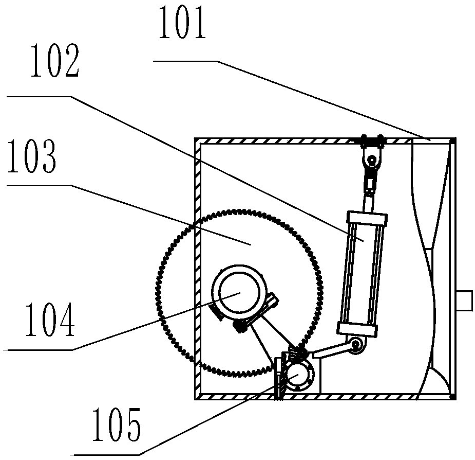
The traditional double-headed saw has a safety shield on each machine head, but it is not fully enclosed. The powder and dust fly on the equipment, which is neither environmentally friendly nor safe.
In view of the many shortcomings of the current traditional equipment that cannot automatically feed and discharge materials, and cannot be used in conjunction with optimized cutting software, and considering that the accuracy of processing equipment is a key factor determining the quality of cutting materials, ordinary sawing machines can no longer meet modern manufacturing requirements. Therefore, the development and application innovation of CNC double-head sawing machine has become one of our research directions today.

Method used


Image

  • Numerical control cutting machine
  • Numerical control cutting machine

Examples


Embodiment Construction

[0022] It should be noted that, in the case of no conflict, the embodiments of the present invention and the features in the embodiments can be combined with each other.

[0023] In describing the present invention, it should be understood that the terms "center", "longitudinal", "transverse", "upper", "lower", "front", "rear", "left", "right", The orientations or positional relationships indicated by "vertical", "horizontal", "top", "bottom", "inner", "outer", etc. are based on the orientation or positional relationships shown in the drawings, and are only for the convenience of describing the present invention Creation and simplification of description, rather than indicating or implying that the device or element referred to must have a specific orientation, be constructed and operate in a specific orientation, and therefore should not be construed as limiting the invention. In addition, the terms "first", "second", etc. are used for descriptive purposes only, and should no...


PUM


Abstract

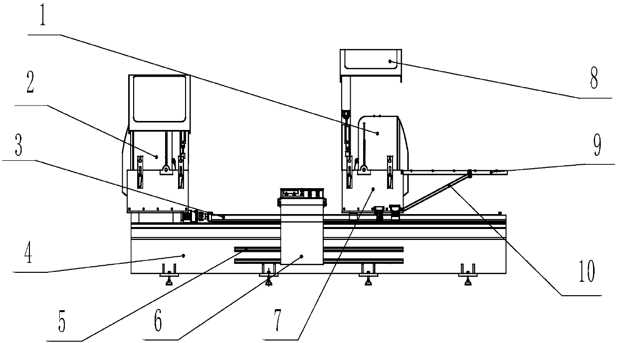
The invention provides a numerical control cutting machine. The numerical control cutting machine comprises a right cutting saw, a left cutting saw, a ball screw, a machine tool base, a linear double-guiding rail, a control box, two saw head seats, a shield, a supporting frame supporting roller, and a supporting frame bracket, the left cutting saw and the right cutting saw are installed on the twosaw head seats correspondingly, by driving of a gear motor, the left cutting saw and the right cutting saw are driven to swing to form a swinging device, the saw head seat provided with the left cutting saw is fixed to the machine tool base through a connecting block, the saw head seat provided with the right cutting saw is matched with the ball screw installed on the machine tool base through aball screw pair, and a servo motor is controlled by the control box to drive the ball screw to drive the left cutting saw and the right cutting saw to move left and right. According to the numerical control cutting machine, multi-angle automatic cutting is realized, the manpower is saved, the labor intensity is lowered, and the safety and environmental protection are achieved.

Description

technical field [0001] The invention belongs to the field of cutting and processing of aluminum materials, and in particular relates to a numerical control cutting machine. Background technique [0002] Since the reform and opening up, after more than 30 years of development, China has become a big country of aluminum profiles, and it is also the world's largest producer and consumer market of aluminum profiles. Common aluminum profiles include aluminum alloy doors and windows, solar photovoltaic modules, broken bridge aluminum, hollow aluminum bars, aluminum alloy trusses and industrial aluminum materials. As an important application material in the field of construction and machinery industry, aluminum profiles are increasingly in demand in modern society, and special processing machinery is gradually developing and improving accordingly. The first process of aluminum profile processing is usually material cutting, also known as blanking. The requirements of this process ...

Claims


Application Information

Patent Timeline
Patent Type & Authority Applications(China)
IPC IPC(8): B23D45/02B23D47/00
Inventor 王红钢
Owner 新昌县捷拓建筑安装有限公司
Learn More