Energy storage unit and refrigeration/insulation container

An energy storage unit and packaging technology, which is used in packaging, transportation and packaging, transportation of passenger cars, etc., can solve the problems of troublesome installation and difficult fixing of the energy storage tube, and achieve the effect of convenient installation and fixing, saving materials and improving production efficiency.

Pending Publication Date: 2019-06-25
TAICANG CIMC REEFER LOGISTICS EQUIP CO LTD +2
View PDF0 Cites 2 Cited by
  • Summary
  • Abstract
  • Description
  • Claims
  • Application Information

AI Technical Summary

Problems solved by technology

[0004] The purpose of the present invention is to solve the problems in the prior art that the energy storage tube is not easy to fix and the installation is troublesome

Method used


Image

  • Energy storage unit and refrigeration/insulation container
  • Energy storage unit and refrigeration/insulation container
  • Energy storage unit and refrigeration/insulation container

Examples


Embodiment 1

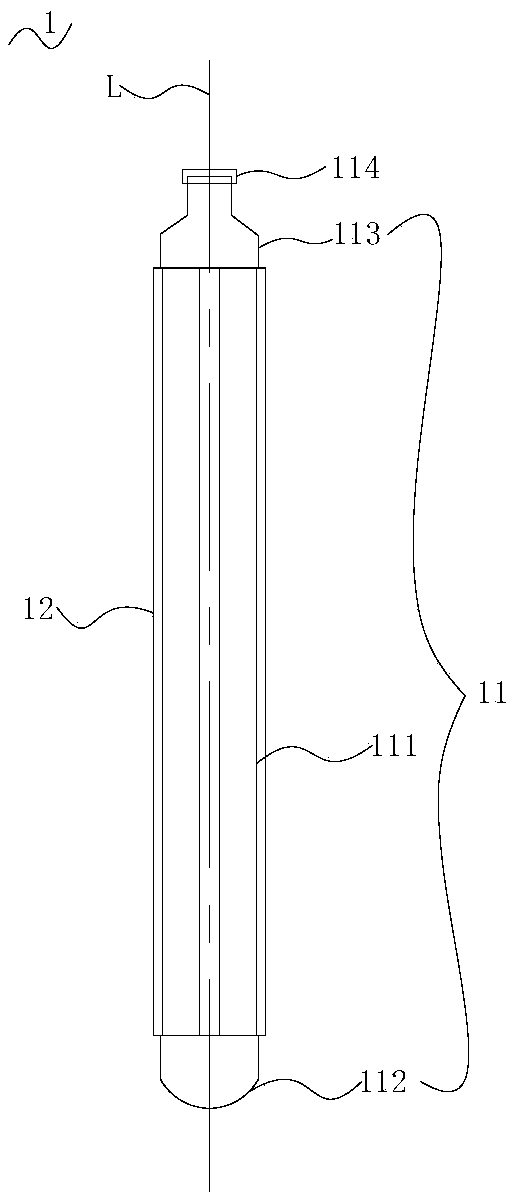
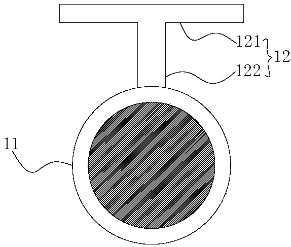
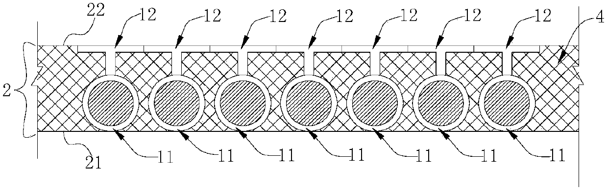
[0027] refer to figure 1 and figure 2 , the present embodiment provides an energy storage unit 1 including an energy storage body 11 and at least one seat 12 . Wherein, the energy storage main body 11 is columnar, and the energy storage main body 11 has an inner cavity, and the inner cavity is used for containing phase change materials. The support 12 is fixed to the energy storage main body 11 , and the support 12 has a bottom plate 121 , and the bottom plate 121 is parallel to the central axis L of the energy storage main body 11 . When the energy storage unit 1 of this embodiment is applied to the field of containers, generally a plurality of them are arranged in a row in the container, and the energy storage units 1 are usually filled with foam material 4 .

[0028] When installing the energy storage unit 1 of this embodiment, it is only necessary to direct the support 12 towards the area to be installed and make the bottom plate 121 adhere to the installation surface. ...

Embodiment 2

[0042] The energy storage unit 1 of the present embodiment is roughly the same as that of the embodiment 1, and its main difference is: refer to Figure 5 , the energy storage unit 1 is provided with a plurality of supports 12 , the energy storage unit 1 in this embodiment includes three supports 12 , and the three supports 12 are arranged at intervals along the circumference of the energy storage body 11 .

[0043] The structures of the energy storage body 11 and the support 12 in this embodiment are the same as those of the energy storage unit 1 in Embodiment 1, and will not be repeated here. In this embodiment, the three supports 12 are respectively one supporting support 12a and two blocking supports 12b. Wherein, the two stop supports 12b are symmetrically arranged on both sides of the support support 12a, and the two stop supports 12b are respectively arranged at both radial ends of the energy storage main body 11 .

[0044] When the energy storage unit 1 of this embodi...


PUM


Abstract

The invention provides an energy storage unit and a refrigeration / insulation container. The energy storage unit includes an energy storage main body and at least one support seat, wherein the energy storage main body is in a column shape and is provided with an inner cavity, and the inner cavity is used for storing phase-change materials; the support seats are fixed to the energy storage main bodyand is provided with a base plate, and the base plate is parallel to the central axis of the energy storage main body. When the energy storage unit is mounted, the support seats are only needed to face towards a to-be-mounted area, and the base plate is attached to a mounting surface. When the base plate is placed on the mounting surface in an attaching mode, the energy storage main body can conveniently maintain a stable placing state in a mounting area, it is no needed that the multiple energy storage units are bound with each other by using fixing tape, compared with an existing energy storage tube, the energy storage unit is more convenient to mount and fix, materials of mounting and fixing are saved, and the production efficiency is effectively improved.

Description

technical field [0001] The invention relates to the fields of energy storage and containers, in particular to an energy storage unit and a refrigerated / insulated container. Background technique [0002] With people's increasing emphasis on environmental protection, energy saving and pollution reduction, the wide application of phase change energy storage materials and related strengthening technologies has increased the research on phase change energy storage material containers. Energy storage material containers currently on the market generally appear in the form of tubes and blocks. Tubular energy storage materials, we call them energy storage tubes. [0003] At present, the commonly used energy storage tube is cylindrical. Although it has enhanced compression resistance, when the cylindrical energy storage tube is installed on the side plate, end plate or floor, because the cylindrical shape is not easy to fix, it must be used between the existing energy storage tubes....

Claims


Application Information

Patent Timeline
Patent Type & Authority Applications(China)
IPC IPC(8): B65D88/74B65D90/00
Inventor 黄国浩杨维廷马兆云王永东柳小伟郭翠群
Owner TAICANG CIMC REEFER LOGISTICS EQUIP CO LTD
Why Eureka
Try Eureka