Calibration method for 2D laser-binocular camera combined calibration

A binocular camera and joint calibration technology, applied in image data processing, instrumentation, computing and other directions, can solve the problems of low precision, difficult to achieve, and inconvenient operation.

Active Publication Date: 2019-06-25
TZTEK TECH
View PDF5 Cites 3 Cited by
  • Summary
  • Abstract
  • Description
  • Claims
  • Application Information

AI Technical Summary

Problems solved by technology

The manual adjustment method has low precision, inconvenient operation, and it is difficult to achieve high consistency

Method used


Image

  • Calibration method for 2D laser-binocular camera combined calibration

Examples


Embodiment Construction

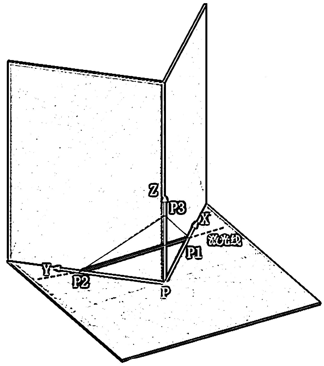
[0014] A calibration method for 2D laser-binocular camera joint calibration: install the 2D laser and the binocular camera on the equipment to be calibrated, and then set the calibration plate directly in front of the equipment to be calibrated. The calibration plate includes three mutually perpendicular planes, and intersect each other in pairs to form the corresponding X-axis, Y-axis, and Z-axis, and one of the planes is provided with a plane calibration feature, and then use the transformation relationship between the 2D laser coordinate system and the calibration plate coordinate system, and the binocular camera coordinates system and the plane calibration feature coordinate system, and the corresponding change relationship formed by the plane calibration feature coordinate system and the calibration plate coordinate system to obtain the transformation relationship between the 2D laser coordinate system and the binocular coordinate system, and complete the joint calibration ...


PUM


Abstract

The invention provides a calibration method for 2D laser-binocular camera combined calibration. Through the practicability of the calibration plate, full automation of 2D laser and binocular camera joint calibration can be achieved, high precision and consistency are achieved, and calibration is suitable for batch production. A 2D laser and a binocular camera are installed on a to-be-calibrated device. A calibration plate is arranged at the front position of the to-be-calibrated equipment. The calibration plate comprises three planes which are perpendicular to each other. every two of the X axes are intersected to form a corresponding X axis, a Y-axis and a Z-axis, one plane is provided with a plane calibration feature; then, a transformation relation between a 2D laser coordinate system and a calibration plate coordinate system is utilized; solving a transformation relation between the 2D laser coordinate system and the binocular coordinate system according to a change relation between the binocular camera coordinate system and the plane calibration feature coordinate system and a corresponding change relation between the plane calibration feature coordinate system and the calibration plate coordinate system, and completing the combined calibration of the 2D laser coordinate system and the binocular coordinate system.

Description

technical field [0001] The invention relates to the technical field of automatic driving, in particular to a calibration method for 2D laser-binocular camera joint calibration. Background technique [0002] In self-driving equipment such as unmanned vehicles and autonomous mobile robots, 2D lasers are often used in conjunction with cameras to supplement the area outside the binocular camera's field of view with 2D laser information; or through 2D laser-binocular camera joint calibration Combined with 3D laser-camera calibration, the coordinate system transformation from 2D laser to 3D laser can be obtained, so that the 2D laser information can be used to supplement the information outside the 3D laser field of view. [0003] In the existing calibration method, the scanning line of the 2D laser is often adjusted by rotation and translation through manual operation, so that it coincides with the camera image or 3D laser data, so as to obtain the coordinate transformation relat...

Claims


Application Information

Patent Timeline
Patent Type & Authority Applications(China)
IPC IPC(8): G06T7/80
CPCY02E30/30
Inventor 杨聪刘军传田乃鲁翁海峰刘克志
Owner TZTEK TECH
Why Eureka
Try Eureka