Housing of portable payment terminal and portable payment terminal

A payment terminal and portable technology, which is applied in the field of payment devices, can solve problems such as inconvenient, unsafe for users, and insufficient security, and achieve the effect of saving time

Inactive Publication Date: 2019-06-25
高玉玲
0 Cites 0 Cited by

AI-Extracted Technical Summary

Problems solved by technology

[0002] With the development and wide application of Internet technology, more and more smart terminal transactions are provided for people. The payment method using smart terminals has become an important payment method in people's daily ...

Method used

Further, printer 21 is fixedly installed in the inside of casing 1 by screw, and display screen 4 is fixedly installed on the operating panel 10 of casing 1 top by screw, makes printer 21 and display screen 4 not shake, and the stability of device is more powerful.
Principle of work: during work, this network security terminal payment device based on the stabilized power supply, for the user, not only can complete the payment by inputting the password on the keyboard 6, but also the fingerprint reader 12 and the sound With the setting of the recognizer 23, the user can verify the identity through the fingerprint and voice reserved in the system terminal, and the whole process is recorded by the camera 11 during use, which gives the ...

Abstract

The invention discloses a housing of a portable payment terminal and a portable payment terminal. The portable payment terminal comprises a housing, a display screen, an alarm device, a fingerprint identifier, a magnetic stripe card reader, a mass sensor, an AT89S51 single-chip microcomputer and a voice recognizer. A switch, the display screen the alarm device, a camera, a keyboard and a fingerprint identifier are arranged outside the housing; a servo motor, a receipt paper tube, a mass sensor and a printer are arranged inside the housing. A storage battery, the voice recognizer and the AT89S51 single-chip microcomputer are arranged at one side of the magnetic stripe card reader. When the terminal is in use, the user can complete payment by a password mode and can carry out identity verification by using the own fingerprint and sound reserved in the system terminal; the whole course is recorded for storage to provide the greatest safety guarantee for the user; when sensing the insufficient weight of the paper tube, the mass sensor arranged in the terminal transmits the information to the AT89S51 single-chip microcomputer; and the AT89S51 single-chip microcomputer controls the alarmdevice to make alarm sounds for warning, so that the user can replace the printing receipt in advance to save the time.

Application Domain

Cash registersProtocol authorisation

Technology Topic

Electric machineryFingerprint +12

Image

  • Housing of portable payment terminal and portable payment terminal
  • Housing of portable payment terminal and portable payment terminal

Examples

  • Experimental program(1)

Example Embodiment

[0014] The following will clearly and completely describe the technical solutions in the embodiments of the present invention with reference to the accompanying drawings in the embodiments of the present invention. Obviously, the described embodiments are only some, not all, embodiments of the present invention. Based on the embodiments of the present invention, all other embodiments obtained by persons of ordinary skill in the art without making creative efforts belong to the protection scope of the present invention.
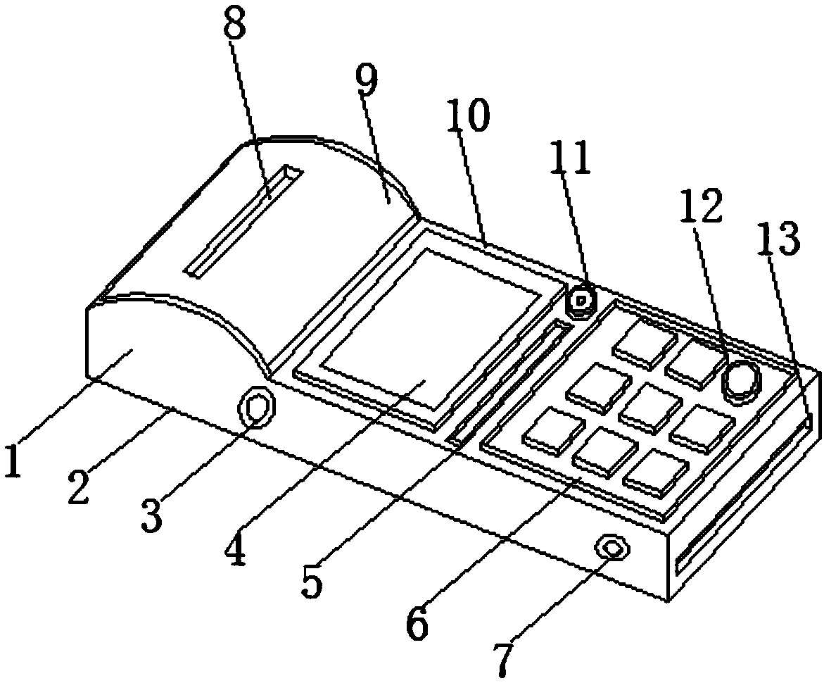
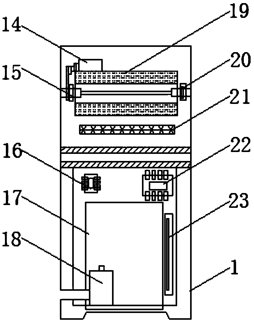
[0015] see Figure 1-2 , the present invention provides a technical solution: a shell of a portable payment terminal and a portable payment terminal, including a shell 1, a base 2, a switch 3, a display screen 4, an alarm 5, a keyboard 6, a charging hole 7, and a ticket outlet 8 , small ticket cover 9, operation panel 10, camera 11, fingerprint reader 12, magnetic stripe card reading port 13, servo motor 14, rotating shaft 15, storage 16, magnetic stripe card reader 17, battery 18, small ticket Paper tube 19, quality sensor 20, printer 21, AT89S51 single-chip microcomputer 22 and voice recognizer 23, the bottom of shell 1 is provided with base 2, one side of shell 1 is provided with switch 3 and charging hole 7, and the top of shell 1 is provided with operation plate 10, one side of the operating panel 10 is provided with a small ticket cover 9, the top of the small ticket cover 9 is provided with a ticket outlet 8, one side of the small ticket cover 9 is provided with a display screen 4, and one side of the small ticket cover 9 is provided with a display screen 4. An alarm 5 is provided on one side of the alarm 5, a camera 11 is provided on one side of the alarm 5, a keyboard 6 is provided on the other side of the alarm 5, a fingerprint reader 12 is provided on the top of the keyboard 6, and the above structures are all arranged on the surface of the shell 1 , one side of the interior of the housing 1 is provided with a servo motor 14, one side of the servo motor 14 is provided with a small ticket paper tube 19 and a rotating shaft 15, the bottom of the small ticket paper tube 19 is provided with a quality sensor 20, and the small ticket paper tube 19 One side of the magnetic stripe card reader 13 is provided with a printer 21, the inside of the magnetic stripe card reader 13 is provided with a magnetic stripe card reader 17, one side of the magnetic stripe card reader 17 is provided with a storage battery 18, and the other side of the magnetic stripe card reader 17 is provided with Voice recognizer 23 is arranged, and the top of magnetic stripe card reader 17 is provided with storage device 16 and AT89S51 single-chip microcomputer 22.
[0016] Further, the small ticket cover 9 is movably connected with the housing 1 through a hinge, and the small ticket cover 9 can be opened or closed along the hinge, which is convenient for replacing printed small tickets.
[0017] Further, the servo motor 14 is connected to the rotating shaft 15 through a transmission belt. When the servo motor 14 rotates, it can drive the rotating shaft 15 to rotate, and at the same time drive the small ticket paper tube 19 to rotate.
[0018] Further, the printer 21 is fixedly installed inside the housing 1 by screws, and the display screen 4 is fixedly installed on the operation panel 10 at the top of the housing 1 by screws, so that the printer 21 and the display screen 4 do not shake, and the stability of the device is stronger.
[0019] Further, switch 3, display screen 4, alarm 5, keyboard 6, camera 11, fingerprint reader 12, magnetic stripe card reading port 13, servo motor 14, rotating shaft 15, storage 16, magnetic stripe card reader 17 , accumulator 18, mass sensor 20, printer 21 and voice recognizer 23 are all electrically connected with AT89S51 single-chip microcomputer 22, guarantee that AT89S51 single-chip microcomputer 22 controls the operation of each electrical component, and accumulator 18 provides the electric energy needed by the device.
[0020] Working principle: when working, the network security terminal payment device based on the regulated power supply, for the user, not only can complete the payment by entering the password on the keyboard 6, but also the fingerprint reader 12 and the voice recognizer 23 The user can verify their identity through the fingerprint and voice reserved on the system terminal, and the whole process is recorded by the camera 11 during use, giving the user the greatest security. Internally, the quality of the device is The sensor 20 can feel the weight of the small ticket paper tube 19 all the time. When the weight reaches below the preset value, the quality sensor 20 transmits the information to the AT89S51 single-chip microcomputer 22, and the AT89S51 single-chip microcomputer 22 controls the alarm 5 to send an alarm reminder. You don't know how to replace the tickets until they run out, which saves time.
[0021] Finally, it should be noted that: the above is only a preferred embodiment of the present invention, and is not intended to limit the present invention. Although the present invention has been described in detail with reference to the foregoing embodiments, for those skilled in the art, it still The technical solutions recorded in the foregoing embodiments may be modified, or some technical features thereof may be equivalently replaced. Any modifications, equivalent replacements, improvements, etc. made within the spirit and principles of the present invention shall be included within the protection scope of the present invention.

PUM

no PUM

Description & Claims & Application Information

We can also present the details of the Description, Claims and Application information to help users get a comprehensive understanding of the technical details of the patent, such as background art, summary of invention, brief description of drawings, description of embodiments, and other original content. On the other hand, users can also determine the specific scope of protection of the technology through the list of claims; as well as understand the changes in the life cycle of the technology with the presentation of the patent timeline. Login to view more.

Similar technology patents

Hotspot video displaying method and device

InactiveCN105872813Ashorten the time
Owner:LETV INFORMATION TECH BEIJING

Method for refreshing e-book reader

InactiveCN102087833Ashorten the timecontinuous reading experience
Owner:上海盛轩网络科技有限公司

Classification and recommendation of technical efficacy words

  • shorten the time
Why Eureka
Try Eureka