

Protective device for agricultural buried line
A protection device and line technology, applied in the field of electrical line equipment, can solve problems such as high maintenance costs and economic losses, achieve high sensitivity, improve safety performance and stability performance, and achieve the effect of remote transceiver
- Summary
- Abstract
- Description
- Claims
- Application Information
AI Technical Summary
Problems solved by technology
Method used
Image

Examples
Embodiment
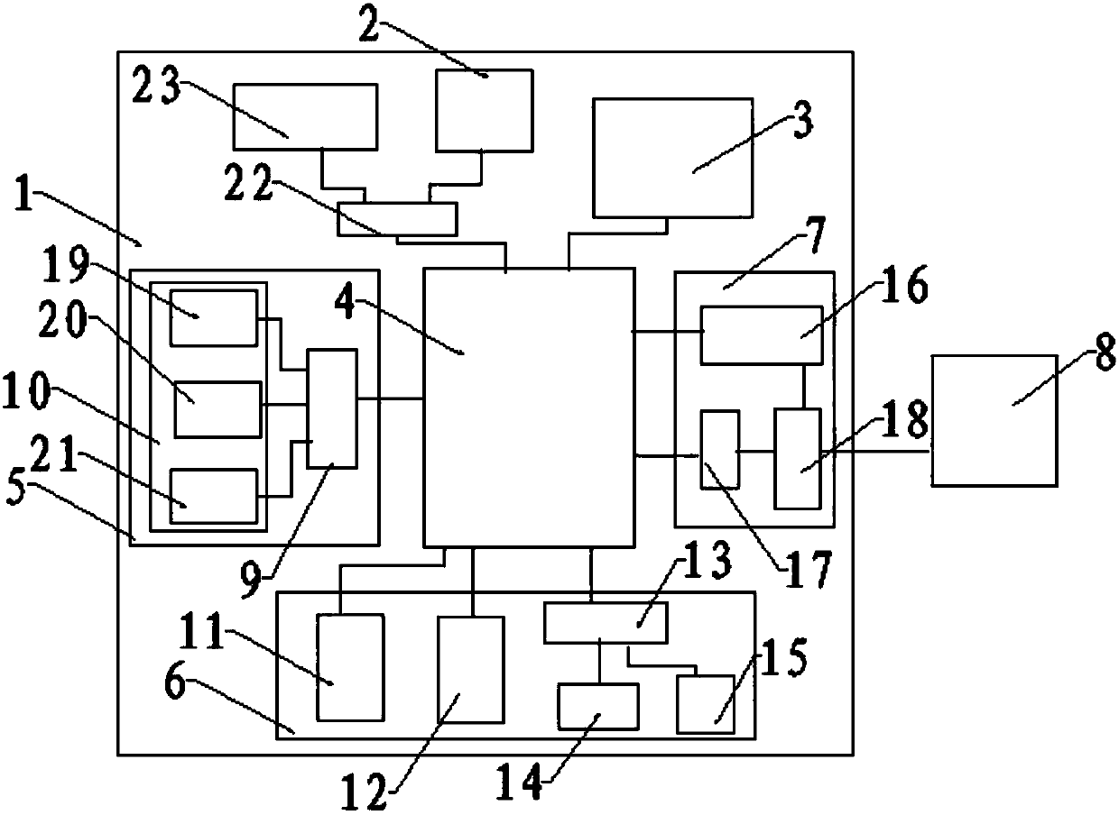
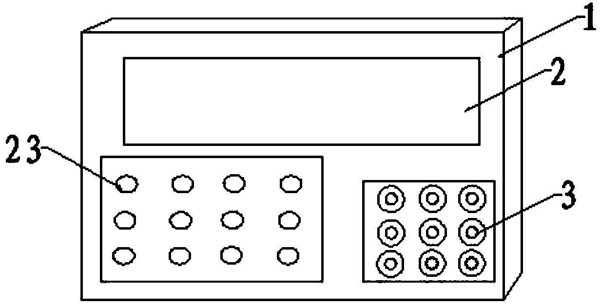
[0014] see figure 1 with figure 2 The present invention provides a technical solution: a protective device for agricultural buried lines, including an installation box 1, the upper surface of the installation box 1 is inlaid with a liquid crystal display 2 and a wiring port 3, and the installation box 1 A core processor 4 is installed, the data input end of the core processor 4 is connected with a data acquisition module 5, the command output end is connected with a protection alarm module 6, and the communication port is connected with a wireless communication module 7, and the wireless communication module 7 is connected There is a remote host computer 8; the data acquisition module 5 includes a data acquisition card 9, and the input end of the data acquisition card 9 is connected with a sampling circuit unit 10; the protection alarm module 6 includes a motor protection circuit breaker 11, a solid state relay 12 and amplifying driver 13, the output end of described amplify...
PUM
 Abstract
Description
Claims
Application Information