Data transmission method, device and system

A data transmission and equipment technology, applied in the field of optical communication, can solve the problems of high complexity and high cost of customized equipment, and achieve the effect of reducing the carrying cost and ensuring the transmission quality

Active Publication Date: 2019-06-25
HUAWEI TECH CO LTD
4 Cites 5 Cited by

AI-Extracted Technical Summary

Problems solved by technology

[0005] The embodiment of the present application provides a device, device and method for data transmis...

Method used

By above-mentioned method, various access business can come access OTN network by ONU equipment, and ONU equipment encapsulates customer data by unified uplink transmission frame format, need not customize according to different business, also reduced like this The complexity of OTN access equipment. In addition, ONU equipment is cheap, which can greatly reduce the cost of access equipment.
[0064] Passive Optical Network (PON) equipment is widely used at present, and its price is relatively low. However, due to its limited transmission distance and single networking form, PON is currently mainly used for broadband access. At present, applications that combine PON and transport networks (for example, OTN) are common in that OTN networks are used as the bearer network of PON networks, so that PON services can be transmitted over longer distances, or provide stronger protection capabilities (for example: provide 1 +1 protection) etc. Different from the existing methods, this application discloses a new OTN device, so that traditional OTN access services can be accessed using ONU devices, so that ONU devices can be used as CPE devices, thereby reducing OTN The cost of customer access equipment. Those skilled in the art know that when the FlexE technology develops into a practical transmission technology, the aforementioned OTN equipment may also be a FlexE equipment.
[0104] The method provided in this embodiment uses the OTN equipment with new functions, so that the network can use the current low-cost ONU equipment to realize customer service access, thereby reducing the cost of customer service network construction. Optionally, the new type of OTN equipment may have a bandwidth adjustment capability, which can realize end-to-end service bandwidth adjustment, so as to meet the requirements of d...

Abstract

The invention discloses a data forwarding method, device and system. In one possible implementation, a data forwarding apparatus includes a transceiver and a processor. Wherein the transceiver receives an uplink data frame sent by an optical network unit (ONU) device. And the processor processes the uplink data frame to obtain a data frame group sent to the same target ONU device. Then, the processor encapsulates this set of data frames into an optical transport network (OTN) data frame, utilizing the transceiver to transmit the OTN data frame. According to the data transmission technology disclosed by the invention, by using the ONU equipment with low price and bearing the service with the bandwidth guarantee requirement to the OTN data frame with the corresponding bandwidth, the equipment cost of bearing the service with the bandwidth guarantee requirement by the transmission network is reduced, and meanwhile, the service transmission quality can also be guaranteed.

Application Domain

Technology Topic

Data transmissionOptical Transport Network +6

Image

  • Data transmission method, device and system
  • Data transmission method, device and system
  • Data transmission method, device and system

Examples

  • Experimental program(5)

Example Embodiment

[0077] Example 1:
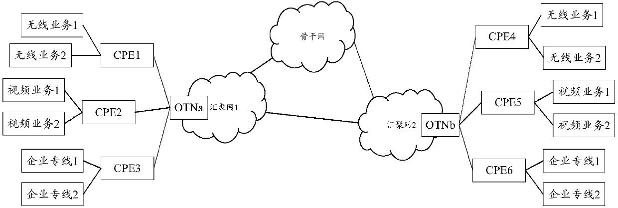
[0078] An embodiment of the present application provides a data processing method, device and system. This embodiment is based on figure 2 As an example, assume that ONU1, ONU2, and OTN1 are devices on the service sending side, and OTN2, ONU4, and ONU3 are devices on the service receiving side. It should be noted that this embodiment assumes that there is no bearer network between the ONU device and the OTN device. In the actual application process, any ONU device can be a sending or receiving device, and the corresponding OTN device is a sending or receiving device. Generally, ONU equipment and OTN equipment usually have the functions of sending and receiving service data at the same time.
[0079] Figure 5 The steps that need to be performed for the data processing of the above equipment are given. The specific description is as follows:
[0080] S501: Send multiple passive optical network (PON) upstream data frames;
[0081] Specifically, ONU devices (for example: ONU1 and ONU2) first encapsulate the received customer data (for example, wireless service 1, wireless service 2, etc.) into a data frame for upstream transmission on the PON network. For example, in Gigabit PON (GPON), when the ONU device sends upstream data, the encapsulation of the service data stipulated by the standard adopts the Gigabit-capable passive optical network encapsulation method (GEM). For another example, a custom PON upstream data frame can be used, and this data frame needs to support the upstream time division burst mechanism in the PON. Then, the ONU device sends these uplink data frames carrying client data through pre-configured time slots. In GPON, this pre-configured time slot constitutes a pipe resource, which is also called a transmitter (ie T-CONT). To simplify the description, the following explanation is limited to the GPON data frame specified by the standard. However, in actual applications, this application does not limit the upstream data transmission format used by the ONU device, but only requires that the ONU device can use dedicated pipe resources and the PON upstream data frame format to send data. In other words, this PON upstream data frame can be customized, but the mechanism for sending the data frame is based on the time-division burst mechanism.
[0082] It should be noted that the PON upstream data frame sent in this step is received by the OTN1 device. Specifically, for the receiving action of the OTN1 device, see Figure 4 The description of step S401 is not repeated here. In other possible implementation manners, the object sent in this step may be other network devices. For details, refer to the description of Embodiment 2-3, which will not be repeated here. Correspondingly, the data frame received by the OTN1 device is not necessarily a PON upstream data frame, but may also be a data frame of other formats, but the data frame of the other format carries the PON upstream data frame. In this embodiment, it is taken as an example that the data frame received by OTN1 is a PON upstream data frame.
[0083] S502: Obtain a first data frame group according to the multiple PON upstream data frames;
[0084] The subject of this step is the OTN1 device. Specifically, after receiving the uplink data frames sent by one or more ONU devices, the OTN1 device needs to group these data frames and allocate corresponding ODU pipeline resources for these data frame groups, so that the data frames carry Customer data can be transmitted in an end-to-end pipeline with guaranteed bandwidth. The advantage of this is that the transmission quality of customer data can be guaranteed, such as packet loss rate, delay, and reliability.
[0085] This step follows Figure 4 The step S402 is similar. The OTN1 device can perform data grouping according to the time division pipeline identifier corresponding to the received PON upstream data frame. Specifically, the uplink data frames with the same time division pipeline identifier are grouped into a group, thereby obtaining one or more data frame groups. For example, for the upstream data frame sent by the ONU device supporting GPON, the OTN1 device can use the allocation identifier (alloc-ID) to distinguish. For other types of PON networks, OTN1 devices can also group according to other pipe resource identification information of the PON to ensure that data frames carrying the same customer data can be divided into the same group.
[0086] In a possible implementation, the OTN1 directly uses the one or more data frame groups obtained above as the first data frame group. In another possible implementation, the OTN1 may further analyze the one or more data frame groups obtained above to obtain the first data frame group. For example, in a GPON network, GEM frames can be parsed and obtained as the first data frame group. For another example, customer data can be parsed, and the customer data frame can be regarded as the first data frame group.
[0087] S503: Encapsulate the first data frame group into an optical transport network (OTN) data frame;
[0088] This step follows Figure 4 The step S403 is similar. Specifically, the OTN1 device selects a suitable ODU data frame for the first data frame group, and encapsulates the data frame in the first data frame group into the ODU data frame. For example, if the service is Fast Ethernet (FE), and the bandwidth of the first data frame group is 100M, then the OTN1 device can select an OTN container of the corresponding bandwidth to carry it. For another example, if the service is two 4.5G wireless services, and the bandwidth of the first data frame group is 9G, then the OTN1 device can select ODUflex with a bandwidth of 9G as the bearer container.
[0089] Optionally, the OTN1 device may also cross the first data frame group before encapsulating the first data frame group into the OTN data frame, so that the data frame group can be switched to a suitable output port for output. Specifically, the crossover may be a time division crossover or a space division crossover.
[0090] S504: Send the OTN data frame;
[0091] Specifically, the OTN1 device converts the OTN data frame into an appropriate OTN frame format and sends it out, for example, it can be converted into an OTU data frame, or a flexible OTN interface data frame (FlexO data frame).
[0092] It should be noted that the OTN1 device sends the OTN data frame to another OTN2 device. This OTN2 device can be a new OTN device explained in this application or a traditional OTN device. In this embodiment, the object sent by the OTN1 device is a new OTN device (ie, OTN2 device) as an example.
[0093] Optionally, the OTN1 device also has the function of sending bandwidth allocation information, so that the bandwidth resource information used by the ONU device can be configured. For example, the OTN1 device can allocate the time slot (or pipe) information used in the uplink transmission of data to its corresponding ONU devices (that is, ONU1 and ONU2). Specifically, the information includes at least a time division pipeline identifier, and the start and end position of the byte of the uplink data frame of the time division pipeline indicated by the time division pipeline identifier. It should be noted that the start and end positions can also be in units of bits or other granularity, and this application does not make any restrictions. For example, in GPON, the overhead of a standard downlink data frame can be used to send this bandwidth allocation information. It should be noted that bandwidth resource information sometimes becomes a bandwidth map. Those skilled in the art can know that the bandwidth map received by each ONU device is the same, and through this bandwidth map, each ONU device can obtain information about the time slot (or bandwidth resource) that it can use.
[0094] Optionally, the OTN1 device may also receive external bandwidth adjustment information, and adjust the used ODU data frame according to this information to change the bandwidth size of the ODU data frame carrying the first data frame group. Furthermore, the OTN1 device can also adjust the bandwidth information of the ONU device accordingly to achieve end-to-end pipe bandwidth adjustment. In a possible implementation, this external bandwidth adjustment information may come from the controller or management system. In another possible implementation, this bandwidth adjustment information may come from the ONU device. Specifically, the bandwidth adjustment information (the calendar of bandwidth usage, that is, the bandwidth used in different time periods) can be delivered to the ONU device in advance. When the bandwidth changes, the ONU device can actively send a request message to the OTN device to request bandwidth adjustment. By coordinating the ODU data frame and the bandwidth change of the ONU device, end-to-end lossless adjustment can be realized. Taking the lossless adjustment method for the adjustment of the OTN pipe bandwidth as an example, if the increase in the bandwidth of the ONU device does not exceed the bandwidth of its corresponding ODU pipe, there is no need to adjust the ODU pipe bandwidth, only the bandwidth of the ONU device. If the increased bandwidth of the ONU device is greater than the bandwidth of the corresponding ODU pipe, the bandwidth of the ODU pipe needs to be adjusted first, and then the bandwidth of the ONU device. Similarly, if the bandwidth reduction of the ONU device does not exceed the minimum adjustment granularity of its corresponding ODU pipe (for example: 1.25G or 2.5G, or smaller), there is no need to adjust the ODU pipe bandwidth, only the bandwidth of the ONU device. If the bandwidth reduction of the ONU device is greater than the minimum adjustment granularity of the bandwidth of the corresponding ODU pipe, the bandwidth of the ONU device is adjusted first, and then the ODU pipe bandwidth is optionally adjusted.
[0095] It should be noted that the object sent in this step is the OTN2 device. In other words, the OTN2 device directly or indirectly receives the OTN data frame sent from the OTN1 device. If it is, the OTN2 device is directly connected to the OTN1 device, and the data reception is direct. If the OTN2 device is connected to the OTN1 device as a network through other devices, then the data reception is indirect.
[0096] S505: Parse multiple second data frames from the OTN data frame carrying the first data frame group;
[0097] This step and the following two steps are executed by the OTN2 device. Specifically, after receiving the OTN data frame that carries the first data frame group, the OTN2 device parses out multiple second data frames from these data frames. Depending on the processing mode of the OTN1 device as the transmitting end, the format of the second data frame is different. For example, the data frame may be a corresponding frame format when the time slot indicated by T-CONT is transmitted. Or, the data frame is in the GEM format or the original client data format.
[0098] S506: Encapsulate the data frames sent to the same destination device among the multiple second data frames into a PON downlink data frame;
[0099] Specifically, depending on the format of the second data frame, the processing of the OTN2 device is different. If the second data frame is a frame format corresponding to T-CONT, the OTN2 device needs to terminate these data frames, and parse out multiple GEM frames from these data frames. Then, the OTN2 device encapsulates the GEM frames that need to be sent to the same destination device among multiple GEM frames into a PON downstream data frame. If the second data frame is a GEM frame, the OTN2 device directly encapsulates the data frames sent to the same destination address in these frames into the PON downstream data frame. If the second data frame is customer data, the OTN2 device needs to encapsulate these data frames into GEM frames first, and then send the GEM frames carrying these data frames to the same destination device and encapsulate them into PON downstream data frames. In other words, the OTN2 device needs to distinguish between the destination device that should receive the data frame and the format of the data frame itself. Then proceed to the next step.
[0100] S507: Send the PON downlink data frame.
[0101] The OTN2 device sends the PON downstream data frame generated in step S506. First of all, depending on different networking structures, the objects sent may be different. In this embodiment, OTN2 is directly sent to ONU equipment (for example: ONU3, ONU4). In other scenarios, such as the scenario described in Embodiment 2-3, the OTN2 device may be sent to other bearer network devices, which will not be repeated here. Secondly, OTN2 also needs to distinguish the destination PON equipment of the PON downstream data frame. In a possible implementation, it can be distinguished by the PON port. For example, in figure 2 In the OTN1 device, there are two ports for connecting the ONU device, one port is connected to two ONU devices, and the other port is connected to one ONU device. Then, OTN1 can distinguish the destination device that should send the data frame through the port number. In another possible implementation manner, it can be distinguished by the ONU identifier, or the ONU identifier and the PON port together. For example, in figure 2 In the OTN2 device, there are two ONU devices connected to the ONU, so they can be distinguished by the ONU device identifier. Or something like Figure 4 The description of step S402 in S402 can also be configured externally, and the OTN1 indirectly determines the sending destination device through other parameters. This application does not make any restrictions on how to distinguish data frames from different destination devices.
[0102] After the ONU device as the receiving side receives the downlink data frame sent by the OTN2 device, it parses out the corresponding service data and sends it to the service destination device connected to it, thus completing the service transmission from the source device through the intermediate transmission network. The process of final delivery to the destination device.
[0103] It should be noted that, optionally, the new OTN device disclosed in this application also needs to have ONU device activation, support operation, management, and maintenance messages to support the normal operation and management of the ONU device.
[0104] The method provided in this embodiment adopts OTN equipment with new functions, so that the network can use the current low-cost ONU equipment to implement customer service access, thereby reducing the cost of customer service network construction. Optionally, the new type of OTN equipment may have bandwidth adjustment capabilities, which can realize end-to-end service bandwidth adjustment, thereby being able to meet the needs of dynamic changes in service bandwidth.
[0105] It should be noted, Figure 5 Take OTN equipment as an example, but Figure 5 The described process also applies to FlexE equipment. The difference is that the OTN data frame needs to be replaced with a FlexE data frame. That is to say, the frame format of the carrier container used is different, so the corresponding data frame processing may be different. For example, before the business data is encapsulated into the FlexE frame, code block conversion processing may be required. Unless otherwise specified, the execution subject of the OTN device embodiment or the FlexE device embodiment mentioned in the following embodiments can be replaced.

Example Embodiment

[0106] Example 2:
[0107] An embodiment of the present application provides another data processing method, device and system. This embodiment is based on figure 2 As an example, assume that ONU1, ONU2, and OTN1 are devices on the service sending side, and OTN2, ONU4, and ONU3 are devices on the service receiving side. It should be noted that, unlike Embodiment 1, this embodiment assumes that there is a bearer network between the ONU1 and the OTN1 device. In other words, the ONU1 device is not directly connected to the OTN1 device, but is interconnected through a bearer network.
[0108] In this embodiment, the steps performed by the ONU device and the OTN device are basically the same as the first embodiment. In addition, optional steps that the OTN device can perform, such as bandwidth allocation, bandwidth adjustment, etc., are the same as those of the OTN device in Embodiment 1. Specifically, see Figure 5 As well as the explanation of the related steps, I won't repeat them here. The steps in this embodiment are different from those in embodiment 1:
[0109] First, the ONU1 device sends multiple PON upstream data frames to the device that bears the network instead of directly sending it to the OTN1 device, that is, execute Image 6 的步骤S601. Correspondingly, the steps performed by the bearer network are also Image 6 show. Image 6 Take the OTN as the bearer network as an example. Specifically, the ingress device of the bearer network executes the following steps after receiving the PON upstream data frame sent by the ONU device.
[0110] S602: At the entrance device, encapsulate the PON upstream data frame into multiple OTN data frames;
[0111] In other words, the device that has received the PON upstream data frame encapsulates these data frames into OTN data frames. After the OTN data frame is transmitted by one or more intermediate devices in the bearer network, it is finally transmitted to the egress device of the bearer network.
[0112] S603: At the egress device, parse the PON upstream data frame from the multiple OTN data frames;
[0113] In this step, the egress device parses out the PON upstream data frame from the multiple received OTN data frames.
[0114] S604: Send multiple passive optical network (PON) upstream data frames;
[0115] In this step, the egress device of the bearer network sends the parsed PON upstream data frame to the OTN1 device.
[0116] Second, the OTN1 device does not receive data directly from the ONU device, but receives the PON upstream data frame from the device carrying the network. But from Image 6 It can be seen that the data frame received by the OTN1 device is not different from the data frame format in Embodiment 1.
[0117] It should be noted that OTN as a bearer network is only one example, and other networks with remote functions can also be used for bearer, such as FlexE and other network technologies with long-distance transmission capabilities. It should also be noted that the bearer network in this embodiment may include intermediate devices ( Image 6 Not shown in ), the intermediate device completes the forwarding of the OTN data frame.
[0118] The method provided in this embodiment adopts OTN equipment with new functions, so that the network can use the current low-cost ONU equipment to implement customer service access, thereby reducing the cost of customer service network construction. Optionally, the new type of OTN equipment may have bandwidth adjustment capabilities, which can realize end-to-end service bandwidth adjustment, thereby being able to meet the needs of dynamic changes in service bandwidth. Furthermore, by adopting a bearer network, the distance and types of business scenarios that OTN can cover are extended.

Example Embodiment

[0119] Example 3:
[0120] An embodiment of the present application provides yet another data processing method, device, and system. This embodiment is based on figure 2 As an example, assume that ONU1, ONU2, and OTN1 are devices on the service sending side, and OTN2, ONU4, and ONU3 are devices on the service receiving side. It should be noted that, unlike Embodiment 1, this embodiment assumes that there is a bearer network between the ONU 2 and the OTN 1 device. In other words, the ONU2 device is not directly connected to the OTN1 device, but is interconnected through a bearer network.
[0121] In this embodiment, the steps performed by the ONU device and the OTN device are basically the same as the first embodiment. In addition, the optional steps that the OTN device can perform, such as bandwidth allocation, bandwidth adjustment, etc., are the same as those of the OTN device in Embodiment 1. Specifically, see Figure 5 And the related step explanation, I won't repeat them here. The steps in this embodiment are different from those in embodiment 1:
[0122] First, the ONU2 device sends multiple PON upstream data frames to the device that bears the network, instead of directly sending it to the OTN1 device, that is, execute Figure 7 的步骤S701. Correspondingly, the steps performed by the bearer network are also Figure 7 Given. Figure 7 Take the OTN as an example. Specifically, the ingress device of the bearer network executes the following steps after receiving the PON upstream data frame sent by the ONU device.
[0123] S702: At the entrance device, encapsulate the PON upstream data frame into multiple OTN data frames;
[0124] In other words, the device that has received the PON upstream data frame encapsulates these data frames into OTN data frames. After the OTN data frame is transmitted by one or more intermediate devices in the bearer network, it is finally transmitted to the egress device of the bearer network.
[0125] S703: Send the multiple OTN data frames;
[0126] The main body of this step is the export equipment of the bearer network. That is, devices directly connected to OTN1 devices in the bearer network. Specifically, the egress device of the bearer network sends the received OTN data frame to the OTN1 device.
[0127] Secondly, the OTN1 device does not receive data directly from the ONU2 device, but from the device that carries the network. Moreover, the received data is no longer a PON upstream data frame, but an OTN data frame that carries the PON upstream data frame.
[0128] Third, the OTN1 device needs to add steps to the received data frame processing, that is, step S704 described below.
[0129] S704: Parse the multiple PON upstream data frames from the multiple OTN data frames.
[0130] Specifically, before the OTN1 device performs the processing described in Embodiment 1 on the data frame, the OTN1 device needs to aggregate and analyze the PON upstream data frame from the received OTN data frame.
[0131] The processes executed by the OTN2 device and the ONU3 device on the receiving side are the same as the OTN2 device and the ONU4 device described in Embodiment 1, and will not be repeated here. The only difference is that the customer data parsed by the ONU4 device in Embodiment 1 is a wireless service, while the customer data parsed by the ONU3 is a video service. Therefore, if the OTN2 device has the ability to allocate bandwidth and adjust the bandwidth for the ONU3 and ONU4 devices, the size of the bandwidth allocated to the two ONU devices and the time division pipeline identifier may be different.
[0132] The method provided in this embodiment adopts OTN equipment with new functions, so that the network can use the current low-cost ONU equipment to implement customer service access, thereby reducing the cost of customer service network construction. Optionally, the new type of OTN equipment may have bandwidth adjustment capabilities, which can realize end-to-end service bandwidth adjustment, thereby being able to meet the needs of dynamic changes in service bandwidth. Further, by adopting the bearer network, the types of business scenarios that the OTN network can cover are extended.

PUM

no PUM

Description & Claims & Application Information

We can also present the details of the Description, Claims and Application information to help users get a comprehensive understanding of the technical details of the patent, such as background art, summary of invention, brief description of drawings, description of embodiments, and other original content. On the other hand, users can also determine the specific scope of protection of the technology through the list of claims; as well as understand the changes in the life cycle of the technology with the presentation of the patent timeline. Login to view more.

Similar technology patents

GPRS optimized encoding method based on network monitoring

InactiveCN101478375AGuaranteed full useGuaranteed transmission qualityError prevention/detection by using return channelSelf adaptiveHandshake
Owner:BEIJING JIAOTONG UNIV

Forward power control method for CDMA system

InactiveCN100362764CGuaranteed transmission qualityComplementary fadingEnergy efficient ICTPower managementError ratioCode division multiple access
Owner:HUAWEI TECH CO LTD

Intelligent video monitoring security system

ActiveCN112066227AAvoid shakingGuaranteed transmission qualityStands/trestlesEmbedded systemComputer hardware
Owner:亳州市鑫联宇电子科技有限责任公司

Classification and recommendation of technical efficacy words

  • Guaranteed transmission quality

Manufacturing method of quartz optical fiber image bundle

ActiveCN102520479AReduce absorption lossGuaranteed transmission qualityGlass making apparatusBundled fibre light guideSkin structureQuartz
Owner:NANJING CHUNHUI SCI & TECH IND

Method for balancing the load of a wireless local area network

InactiveUS7558208B2Guaranteed transmission qualityError preventionTransmission systemsMethod selectionLow load
Owner:INFINEON TECH TAIWAN

Scalable layered coding based multi-path transmission scheme

InactiveCN102364962AEfficient and reliable transmissionGuaranteed transmission qualityTelevision systemsDigital video signal modificationTelecommunicationsMultipath transmission
Owner:NANJING UNIV OF POSTS & TELECOMM
Why Eureka
Try Eureka