A method, device and system for data transmission
A data transmission and equipment technology, applied in the field of optical communication, can solve the problems of high complexity and high cost of customized equipment, and achieve the effect of reducing the carrying cost and ensuring the transmission quality
- Summary
- Abstract
- Description
- Claims
- Application Information
AI Technical Summary
Problems solved by technology
Method used
Image

Examples
Embodiment 1
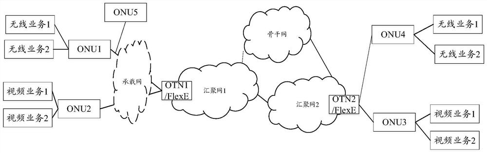
[0078] An embodiment of the present application provides a data processing method, device and system. This embodiment takes figure 2 Take the network scenario as an example, assuming that ONU1, ONU2, and OTN1 are devices on the service sending side, and OTN2, ONU4, and ONU3 are devices on the service receiving side. It should be noted that this embodiment assumes that there is no bearer network between the ONU device and the OTN device. In the actual application process, any ONU device can be a sending or receiving device, and the corresponding OTN device can be a sending or receiving device. Generally, the ONU equipment and the OTN equipment usually have the functions of sending and receiving service data at the same time.
[0079] Figure 5 The steps that need to be executed for the data processing of the above-mentioned equipment are given. The specific description is as follows:
[0080] S501: Send multiple passive optical network (PON) uplink data frames;
[0081] ...
Embodiment 2
[0107] An embodiment of the present application provides another data processing method, device and system. This embodiment takes figure 2 Take the network scenario as an example, assuming that ONU1, ONU2, and OTN1 are devices on the service sending side, and OTN2, ONU4, and ONU3 are devices on the service receiving side. It should be noted that, different from Embodiment 1, this embodiment assumes that there is a bearer network between the ONU1 device and the OTN1 device. That is to say, the ONU1 equipment is not directly connected to the OTN1 equipment, but is interconnected through a bearer network.
[0108] In this embodiment, the steps performed by the ONU device and the OTN device are basically the same as those in Embodiment 1. In addition, the optional steps executable by the OTN device, such as bandwidth allocation and bandwidth adjustment, are the same as those of the OTN device in Embodiment 1. Specifically, see Figure 5 And related step explanations, which wi...
Embodiment 3
[0120]An embodiment of the present application provides yet another data processing method, device and system. This embodiment takes figure 2 Take the network scenario as an example, assuming that ONU1, ONU2, and OTN1 are devices on the service sending side, and OTN2, ONU4, and ONU3 are devices on the service receiving side. It should be noted that, different from Embodiment 1, this embodiment assumes that there is a bearer network between the ONU2 device and the OTN1 device. That is to say, the ONU2 equipment is not directly connected to the OTN1 equipment, but is interconnected through a bearer network.
[0121] In this embodiment, the steps performed by the ONU device and the OTN device are basically the same as those in Embodiment 1. In addition, the optional steps executable by the OTN device, such as bandwidth allocation and bandwidth adjustment, are the same as those of the OTN device in Embodiment 1. Specifically, see Figure 5 And related step explanations are no...
PUM
 Abstract
Description
Claims
Application Information
 - Generate Ideas
- Intellectual Property
- Life Sciences
- Materials
- Tech Scout
- Unparalleled Data Quality
- Higher Quality Content
- 60% Fewer Hallucinations
Browse by: Latest US Patents, China's latest patents, Technical Efficacy Thesaurus, Application Domain, Technology Topic, Popular Technical Reports.
© 2025 PatSnap. All rights reserved.Legal|Privacy policy|Modern Slavery Act Transparency Statement|Sitemap|About US| Contact US: help@patsnap.com