Automatic assembly equipment for fittings of power distributing cabinet

A technology for automatic assembly and power distribution cabinets, applied in metal processing equipment, assembly machines, manufacturing tools, etc., to achieve the effects of reducing recovery errors, high synchronization, and reducing production costs

Active Publication Date: 2019-06-28
国网甘肃省电力公司甘南供电公司
View PDF7 Cites 3 Cited by
  • Summary
  • Abstract
  • Description
  • Claims
  • Application Information

AI Technical Summary

Problems solved by technology

[0005] The purpose of the present invention is to address the deficiencies of the prior art, by setting the tightening mechanism to cooperate with the forming mechanism to automatically install the neutral wire on the wiring board and switch after being bent and formed, and at the same time use the formed zero wire to tighten and synchronously complete the butt wiring The pressing work above the board and the switch solves the technical problem that when the neutral wire is assembled with the switch and the wiring board, the position of the switch and the wiring board needs to be positioned to avoid affecting the stable work of the nut tightening the neutral wire

Method used


Image

  • Automatic assembly equipment for fittings of power distributing cabinet
  • Automatic assembly equipment for fittings of power distributing cabinet
  • Automatic assembly equipment for fittings of power distributing cabinet

Examples


Embodiment 1

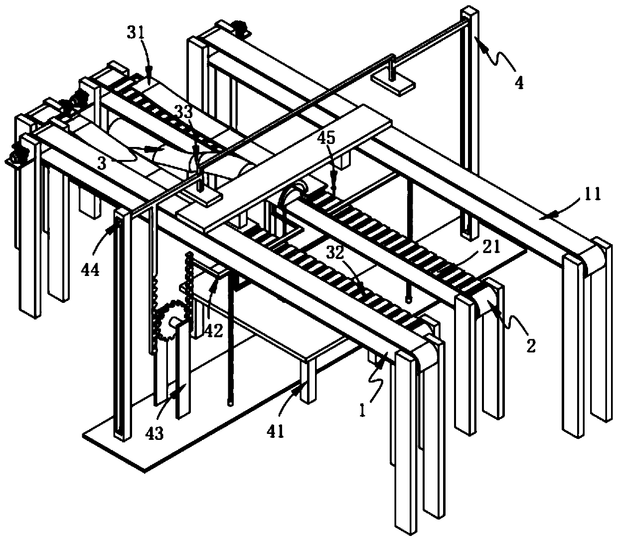
[0073] Such as figure 1 , Picture 10 , Picture 11 with Picture 12 As shown, an automatic assembly equipment for power distribution cabinet accessories includes:

[0074] The first feeding mechanism 1 is composed of two sets of symmetrically arranged transmission components a11;

[0075] The second feeding mechanism 2 is arranged between the two sets of transmission components a11, and it is composed of two sets of symmetrically arranged transmission components b21;

[0076] The forming mechanism 3, the forming mechanism 3 includes a positioning assembly 31 arranged above the transmission assembly b21, a pulling assembly 32 slidably arranged on the positioning assembly 31, and a component located between the two sets of the transmission assembly b21 Arch assembly 33; and

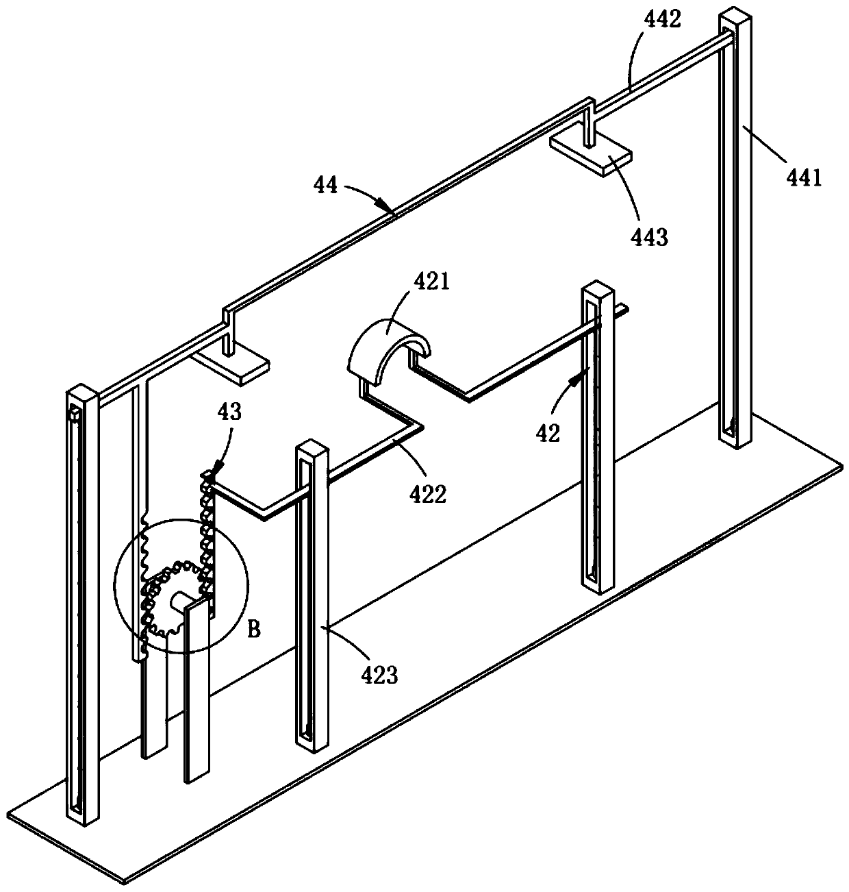
[0077] The tightening mechanism 4 includes a lifting assembly 41 mounted on the arching assembly 33, a hoop assembly 42 located above the lifting assembly 41 and below the transmission assembly a11, and mounted o...

Embodiment 2

[0126] Such as Image 6 As shown, the components that are the same as or corresponding to those in the first embodiment adopt the reference numerals corresponding to the first embodiment. For the sake of simplicity, only the differences from the first embodiment are described below. The difference between the second embodiment and the first embodiment is:

[0127] Further, such as Image 6 As shown, the pulling assembly 32 is arranged on the belt 114 and arranged in several groups at equal intervals along the length direction of the belt 114, which includes:

[0128] A sliding groove 321, the sliding groove 321 is arranged across the belt 114;

[0129] A sliding block 322, the sliding block 322 is slidably arranged on the sliding groove 321 and sliding along the length of the sliding groove 321, the sliding surface of the lower surface of the sliding block 322 is smoothly arranged;

[0130] Bumps 323, the bumps 323 are evenly arranged on the upper surface of the slider 322;

[0131] St...


PUM


Abstract

The invention relates to a piece of automatic assembly equipment for fittings of a power distributing cabinet. The automatic assembly equipment comprises a first feeding mechanism, a second feeding mechanism, a shaping mechanism and a tightening mechanism, wherein the shaping mechanism comprises a positioning component, pulling components and an arching component, wherein the positioning componentis arranged above conveying components b, the pulling components are glidingly arranged on the positioning component, and the arching component is located between the two sets of conveying componentsb; and the tightening mechanism comprises a lifting component, a hoop component, a linkage component, a pressing-down component and locking components, wherein the lifting component is arranged on the arching component, the hoop component is located above the lifting component and below the conveying components a, the linkage component is arranged on the hoop component and cooperates with the hoop component to synchronously drive, the pressing-down component is located above the conveying components a and cooperates with the hoop component to synchronously drive, and the locking components are symmetrically arranged on the lifting assembly. The automatic assembly equipment disclosed by the invention solves the problem that a switch and a wiring board need to be fixed in position when a null line is assembled with the switch and the wiring board, and otherwise, the stable operation of hooping the null line by a nut is influenced.

Description

Technical field [0001] The invention relates to the technical field of power distribution cabinet materials, in particular to an automatic assembly equipment for power distribution cabinet accessories. Background technique [0002] Power distribution cabinets are divided into power distribution cabinets, lighting distribution cabinets, and metering cabinets, which are the final equipment of the power distribution system. The distribution cabinets are the collective name for the motor control center. The distribution cabinets are used in situations where the load is relatively dispersed and there are fewer circuits. ; The motor control center is used in situations where the load is concentrated and there are many circuits. They distribute the electric energy of a certain circuit of the upper-level power distribution equipment to the nearby load. This level of equipment should provide protection, monitoring and control of the load. [0003] The patent document with the patent number ...

Claims


Application Information

Patent Timeline
Patent Type & Authority Applications(China)
IPC IPC(8): B23P21/00
Inventor 王子轩陆一杰蔡泽楷陈建清
Owner 国网甘肃省电力公司甘南供电公司
Why Eureka
Try Eureka