Conical surface centering structure and assembly method

An assembly method and tapered surface technology, applied in the direction of workpiece clamping devices, manufacturing tools, etc., can solve the problems of large rotor vibration, difficult disassembly, large radial thermal deformation of the centering surface, etc., and achieve good centering and good centering , the effect of improving stability

Active Publication Date: 2019-06-28
AECC HUNAN AVIATION POWERPLANT RES INST
View PDF6 Cites 4 Cited by
  • Summary
  • Abstract
  • Description
  • Claims
  • Application Information

AI Technical Summary

Problems solved by technology

[0003] The invention provides a conical surface centering structure and an assembly method to solve the technical problems of large radial thermal deformation at the cen

Method used


Image

  • Conical surface centering structure and assembly method
  • Conical surface centering structure and assembly method
  • Conical surface centering structure and assembly method

Examples


Example Embodiment

[0028] The embodiments of the present invention will be described in detail below with reference to the accompanying drawings, but the present invention can be implemented in many different ways defined and covered by the claims.
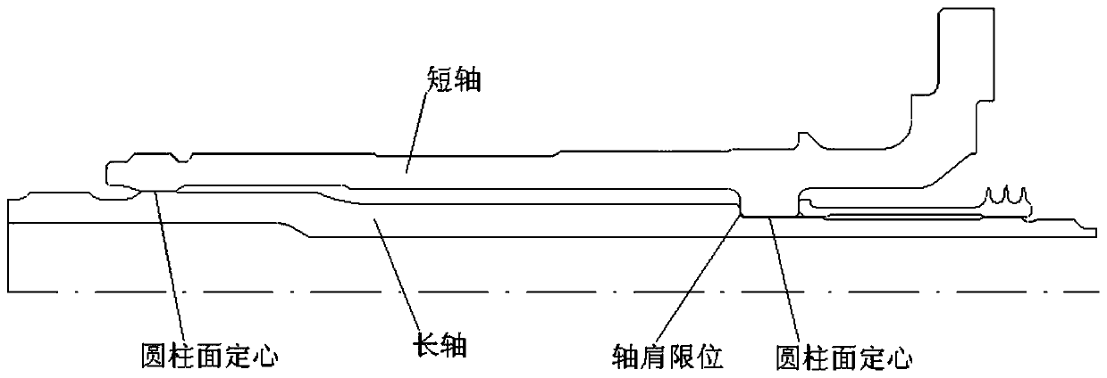
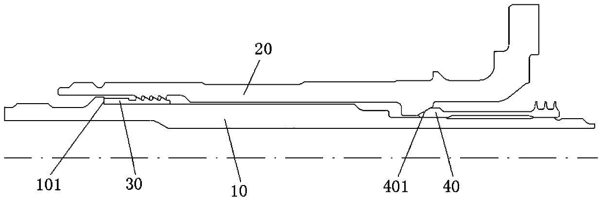
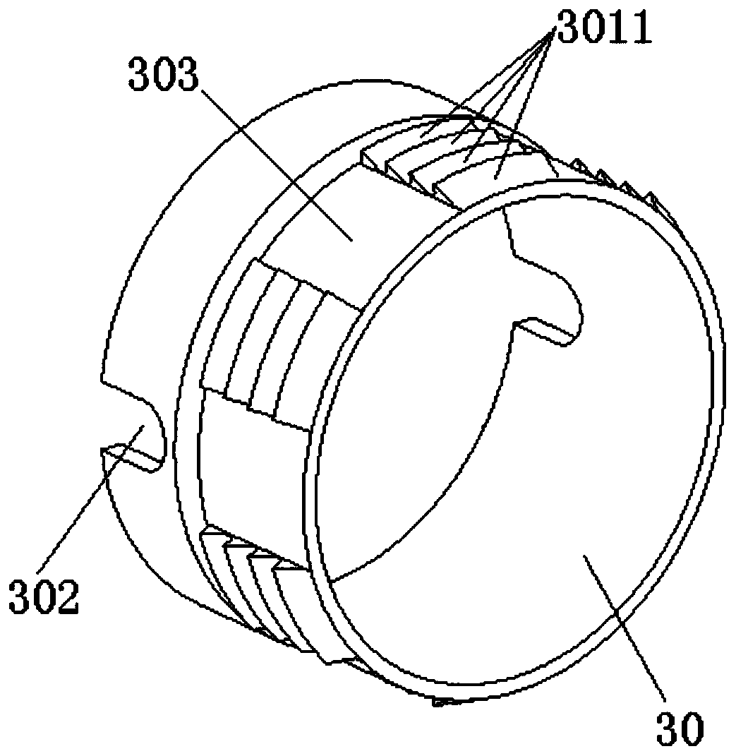
[0029] Reference figure 2 , The preferred embodiment of the present invention provides a cone centering structure, comprising: an inner rotating shaft 10, the inner rotating shaft 10 is coaxially mounted with an outer rotating shaft 20, and the outer circle of the first end of the inner rotating shaft 10 is provided with an annular For the limiting shoulder 101, the outer circle of the second end of the inner rotating shaft 10 is machined with an outer thread. A first limiting ring 30 is installed on the outer circle of the first end of the inner rotating shaft 10, the first limiting ring 30 is located inside the limiting shoulder 101 and the end of the first limiting ring 30 abuts against the limiting shoulder 101 , And the outer ring surface of the ...


PUM


Abstract

The invention discloses a conical surface centering structure and an assembly method. The conical surface centering structure comprises an inner rotating shaft, wherein an outer rotating shaft is coaxially arranged outside the inner rotating shaft; an annular limiting shaft shoulder is arranged on the outer circle of the first end of the inner rotating shaft; the outer circle of the second end ofthe inner rotating shaft is provided with external threads; a first limiting ring is arranged on the outer circle of the first end of the inner rotating shaft; the first limiting ring is arranged at the inner side of the limiting shaft shoulder, and the end the first limiting ring abuts against the limiting shaft shoulder; the outer ring surface of the first limiting ring fits with the conical surface of the inner peripheral wall of the outer rotating shaft; a second limiting ring is arranged on the outer circle of the second end of the inner rotating shaft; the outer ring surface of the second limiting ring fits with the conical surface of the inner peripheral wall of the outer rotating shaft; the fitting direction of the outer ring surface of the second limiting ring and the conical surface of the inner peripheral wall of the outer rotating shaft is opposite to the fitting direction of the outer ring surface of the first limiting ring and the conical surface of the inner peripheral wall of the outer rotating shaft; a locking nut in threaded connection with the screw threads is arranged on the outer circle of the second end of the inner rotating shaft; and the end of the locking nut abuts against the end of the second limiting ring.

Description

technical field [0001] The invention relates to the field of aero-engines, in particular to a conical surface centering structure. Furthermore, the invention also relates to an assembly method for assembling the conical surface centering structure. Background technique [0002] At present, the aero-engine rotor system widely uses the assembly method of cylindrical surface centering and shaft shoulder axial limit, such as figure 1 As shown, it is used to ensure the reliable connection between the parts of the rotor system. Due to the high ambient temperature of the engine rotor and the large temperature gradient, there is a problem of thermal deformation mismatch between related parts. During the working process of the engine, the radial gap at the centering surface of the cylinder is too large, which in turn causes large vibration of the rotor and serious Sometimes it will cause the engine to rotate, the stator to scrape and grind, induce the engine to stop, and eventually...

Claims


Application Information

Patent Timeline
IPC IPC(8): B25B11/00
Inventor 余索远王芳卢波
Owner AECC HUNAN AVIATION POWERPLANT RES INST
Why Eureka
Try Eureka