Railway vehicle automatic parking device and loading method
A technology for automatic parking and railway vehicles, which is applied to the operating mechanism of railway vehicle brakes, railway car body parts, railway braking systems, etc., which can solve problems such as release omissions, low efficiency, and long working hours, so as to increase operational safety performance, improved operational safety, and reduced turnaround time
- Summary
- Abstract
- Description
- Claims
- Application Information
AI Technical Summary
Problems solved by technology
Method used
Image
Examples
Embodiment 1
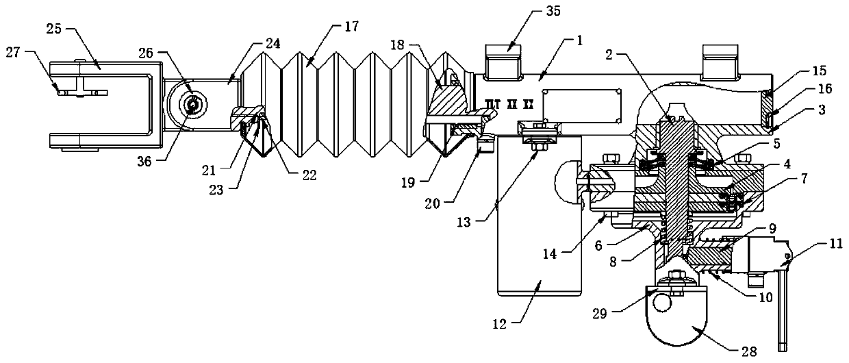
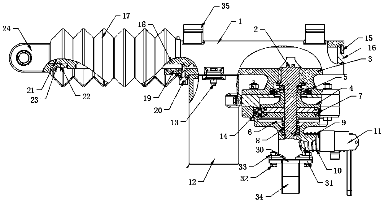
[0030] Such as Figure 1-5 As shown, the present invention provides an automatic parking device for railway vehicles, including a fixed seat 1, a deadbolt valve stem diaphragm assembly 2 is fixedly installed on the bottom side of the fixed seat 1, and the outer end of the deadbolt valve stem diaphragm assembly 2 The upper side is fixed with an upper valve body composition 3, and the bottom of the upper valve body composition 3 is fixedly installed with a middle valve body 4, and a valve body fixing plate 5 on a small membrane plate is installed between the upper valve body composition 3 and the middle valve body 4. The bottom of the middle valve body 4 is fixedly installed with the lower valve body composition 6, the upper diaphragm plate and the lower valve body fixed pressure plate 7 are installed between the middle valve body 4 and the lower valve body composition 6, the latch valve rod diaphragm assembly 2 and the lower valve body A compression spring A8 is installed betwe...
Embodiment 2
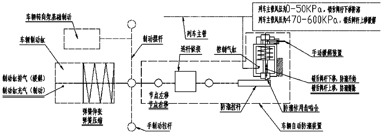
[0041] The invention provides a method for adding an automatic parking device for railway vehicles, the specific steps are as follows:
[0042] A: When the anti-rolling operation is required for the vehicle in the braking state after parking, the air pressure of the brake pipe is emptied to 0-50kPa, and the automatic anti-rolling device of the vehicle enters the anti-rolling reserve position. For the C80 type railway freight car, an anti-rolling The position of the brake is located on the side of the hand brake and the side of the non-hand brake of the vehicle. By adding a set of connecting rod mechanism, the hinged push rod of the anti-roller is connected with the pull rod of the anti-roller. The brake cylinder of the vehicle is connected with the rod The telescoping corresponds to the anti-slip pull rod. The connecting rod mechanism and the support of the vehicle automatic anti-slip device are welded and fixed on the required position of the position end platform of the C80 v...
PUM
 Abstract
Description
Claims
Application Information
 - R&D
- Intellectual Property
- Life Sciences
- Materials
- Tech Scout
- Unparalleled Data Quality
- Higher Quality Content
- 60% Fewer Hallucinations
Browse by: Latest US Patents, China's latest patents, Technical Efficacy Thesaurus, Application Domain, Technology Topic, Popular Technical Reports.
© 2025 PatSnap. All rights reserved.Legal|Privacy policy|Modern Slavery Act Transparency Statement|Sitemap|About US| Contact US: help@patsnap.com


