A waste material removal system

A suction cup and cylinder technology, applied in the field of waste material removal system, can solve the problem of narrow application scope and achieve the effect of wide application scope

Active Publication Date: 2021-02-12
HANS LASER TECH IND GRP CO LTD
View PDF5 Cites 0 Cited by
  • Summary
  • Abstract
  • Description
  • Claims
  • Application Information

AI Technical Summary

Problems solved by technology

[0004] The invention provides a waste material removal system, which can solve the problem that the existing waste material removal system can be applied to remove waste materials of a specific shape and has a narrow application range

Method used


Image

  • A waste material removal system
  • A waste material removal system
  • A waste material removal system

Examples


Embodiment Construction

[0020] In order to make the purpose, features, and advantages of the present invention more obvious and understandable, the technical solutions provided by the embodiments of the present invention will be clearly and completely described below in conjunction with the accompanying drawings provided by the embodiments of the present invention. Obviously, the described The embodiments are only some of the embodiments of the present invention, but not all of them. Based on the embodiments provided by the present invention, all other embodiments obtained by those skilled in the art without creative efforts fall within the protection scope of the present invention.

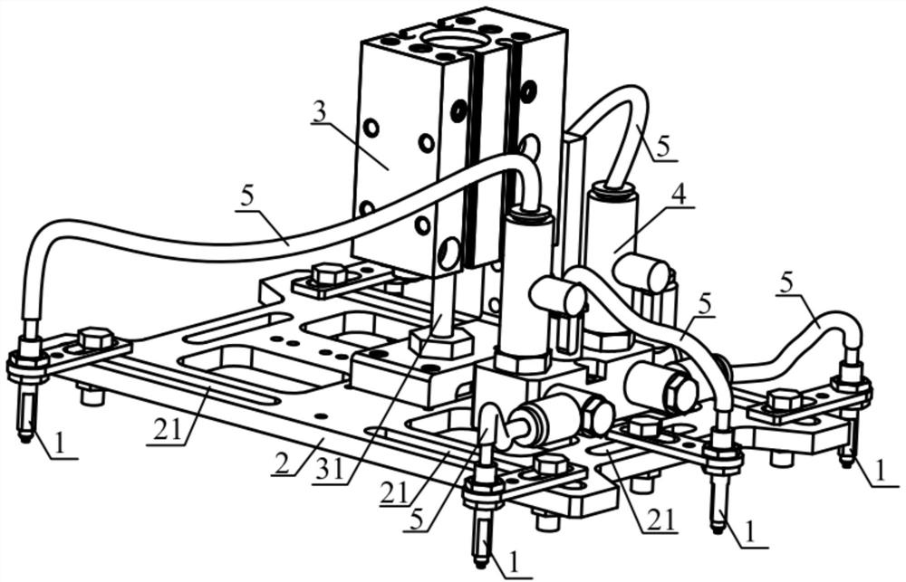
[0021] see figure 1 and figure 2 , figure 1 The waste material removal system provided by the first embodiment of the present invention, figure 2 It is a schematic structural diagram of the waste material removal system provided in the first embodiment of the present invention, combined with figure 1 and figure ...


PUM


Abstract

The invention provides a waste material removal system, which relates to the field of cutting. The waste material removal system includes: a suction cup, a suction cup mounting plate, a lifting cylinder and a collector block. An adjustment slot is provided on the suction cup mounting plate, and the adjustment slot runs through two opposite long and wide surfaces of the suction cup mounting plate. The suction cup is slidably installed in the adjusting groove. The suction cup is provided with an air guide hole passing through the suction cup in the length direction of the suction cup, and the collector block is connected to one end of the air guide hole of the suction cup through a conduit. The output shaft of the lift cylinder is fixed on the suction cup mounting plate. The invention can solve the problem that the existing waste material removal system is suitable for removing waste material of a specific shape and has a narrow application range.

Description

technical field [0001] The invention relates to the cutting field, in particular to a waste material removal system. Background technique [0002] When a cutting system is used to cut a panel, the waste materials after cutting will be concentrated in the cutting system. In order to prevent the waste materials from adversely affecting the cutting, it is necessary to remove the waste materials after cutting from the cutting system. [0003] The existing waste material removal system generally sucks the waste material through a fixed-position vacuum suction cup and removes the waste material from the cutting system. This kind of waste material removal system is ubiquitous and can only be applied to remove waste material of a specific shape. Issues such as narrow scope of application. Contents of the invention [0004] The invention provides a waste material removal system, which can solve the problem that the existing waste material removal system is suitable for removing wa...

Claims


Application Information

Patent Timeline
Patent Type & Authority Patents(China)
IPC IPC(8): B65G47/91
Inventor 赵伟朱晓枫迟彦龙王祥何云尹建刚高云峰
Owner HANS LASER TECH IND GRP CO LTD
Why Eureka
Try Eureka