Convenient-to-operate textile drying oven
A convenient operation, oven technology, applied in drying, dryer, progressive dryer and other directions, can solve the problems of long working hours, high labor intensity, etc., to solve the problem of labor force, improve work efficiency and improve work integration. Effect
- Summary
- Abstract
- Description
- Claims
- Application Information
AI Technical Summary
Problems solved by technology
Method used
Image
Examples
Embodiment 1
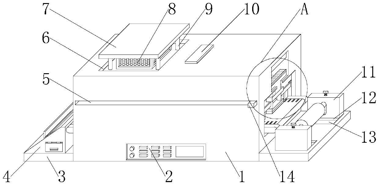
[0032] refer to figure 1 with 7 , a textile oven that is easy to operate, including an oven body 1, a third chute 34 is opened on the inner top of the oven body 1, and a third slider 36 is slidably connected to the side wall of the third chute 34, the third slider The bottom end of 36 is fixedly installed with linear drive plate 44, the top both sides of linear drive plate 44 runs through and is movably connected with two telescopic rods 42, and the bottom end of two telescopic rods 42 is fixedly connected with lifting plate 43, and the bottom of lifting plate 43 The bottom end is fixedly connected with a slow pressure plate 41, and the lower surface of the slow pressure plate 41 is coated with Teflon; one side of each telescopic rod 42 is fixedly connected with a limit plate 38, and the two limit plates 38 are coplanar and symmetrical Setting, the middle part of the bottom end of the limiting plate 38 is fixedly connected with a clamping plate 39, the inner middle part of th...
Embodiment 2
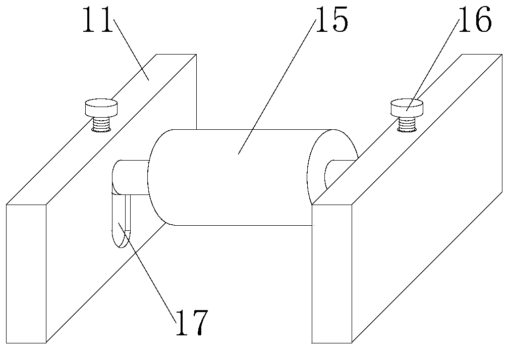
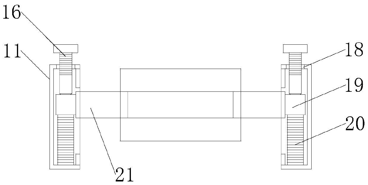
[0035] refer to Figure 1-Figure 7 , a textile oven that is easy to operate, comprising an oven body 1, a third chute 34 is provided on the inner top of the oven body 1, and a third slider 36 is slidably connected to the side wall of the third chute 34, the third slider The bottom end of 36 is fixedly installed with linear drive plate 44, and the top both sides of linear drive plate 44 runs through and is movably connected with two telescopic rods 42, and the bottom end of two telescopic rods 42 is fixedly connected with lifting plate 43, and each telescopic rod One side of 42 is fixedly connected with a limiting plate 38, and the two limiting plates 38 are coplanar and symmetrically arranged. The middle part of the bottom end of the limiting plate 38 is fixedly connected with a clamping plate 39, and the inner middle part of the oven body 1 runs through and A conveyor belt 23 is fixedly installed, and several card slots 40 are provided on both sides of the top of the conveyor...
Embodiment 3
[0040] refer to figure 1 , Figure 4 with Figure 7 , a textile oven that is easy to operate, including an oven body 1, a third chute 34 is opened on the inner top of the oven body 1, and a third slider 36 is slidably connected to the side wall of the third chute 34, the third slider The bottom end of 36 is fixedly installed with linear drive plate 44, and the top both sides of linear drive plate 44 runs through and is movably connected with two telescopic rods 42, and the bottom end of two telescopic rods 42 is fixedly connected with lifting plate 43, and each telescopic rod One side of 42 is fixedly connected with a limiting plate 38, and the two limiting plates 38 are coplanar and symmetrically arranged. The middle part of the bottom end of the limiting plate 38 is fixedly connected with a clamping plate 39, and the inner middle part of the oven body 1 runs through and A conveyor belt 23 is fixedly installed, and several card slots 40 are provided on both sides of the top...
PUM
 Abstract
Description
Claims
Application Information
 - R&D
- Intellectual Property
- Life Sciences
- Materials
- Tech Scout
- Unparalleled Data Quality
- Higher Quality Content
- 60% Fewer Hallucinations
Browse by: Latest US Patents, China's latest patents, Technical Efficacy Thesaurus, Application Domain, Technology Topic, Popular Technical Reports.
© 2025 PatSnap. All rights reserved.Legal|Privacy policy|Modern Slavery Act Transparency Statement|Sitemap|About US| Contact US: help@patsnap.com


