
Precession fluid turbine

A fluid and turbine technology, applied in the direction of machines/engines, hydroelectric power generation, mechanical equipment, etc., can solve the problems of non-processing loss and achieve the effect of increasing efficiency

Active Publication Date: 2019-06-28
CZECH TECHN UNIV & PRAGUE FACULTY OF CIVIL ENG +1
View PDF14 Cites 0 Cited by
  • Summary
  • Abstract
  • Description
  • Claims
  • Application Information

AI Technical Summary

Problems solved by technology

[0005] A common drawback of all known rolling or precessing machines / turbines is that they do not deal with the losses caused by the precessing motion of the shaft in the fluid, nor provide an easy and reliable protection of the current generator from water ingress

Method used


Image

  • Precession fluid turbine
  • Precession fluid turbine
  • Precession fluid turbine

Examples


Embodiment Construction

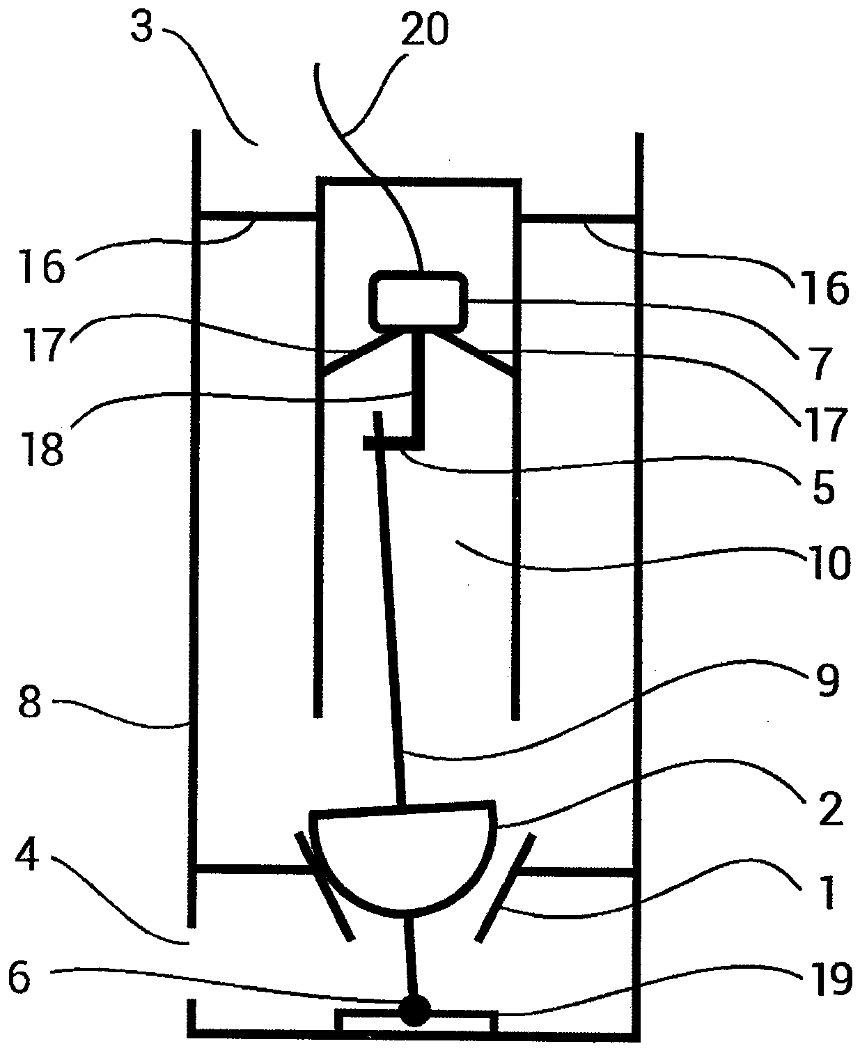
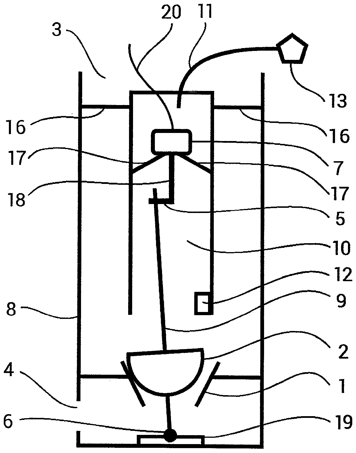
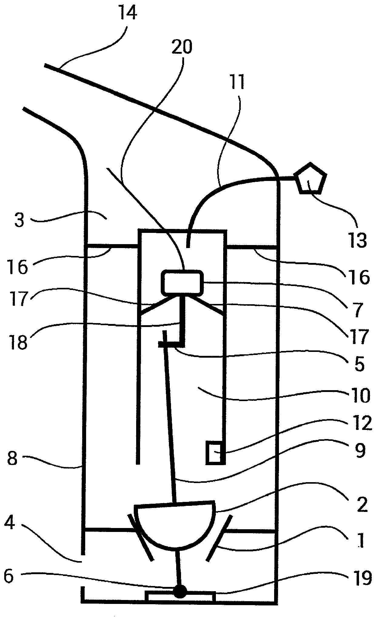
[0014] according to figure 1 The precessing fluid turbine comprises a fluid reservoir 8 having a fluid inlet opening 3 and a fluid outlet opening 4 . The stator nozzle 1 is arranged in a fluid reservoir 8 between a fluid inlet opening 3 and a fluid outlet opening 4 . Arranged in the stator nozzle 1 is a vaneless rolling rotor 2 with a shaft 9 . The rolling rotor 2 can have any shape of revolution.

[0015] The rolling rotor 2 is mounted on a holding device 6 . The holding device 6 may consist of any known mechanism which enables the rotor 2 to roll in a swivel manner along the inner wall of the stator nozzle 1 . exist figure 1 In the embodiment of the present invention, the holding device 6 comprises a rod-shaped support firmly connected to the bottom of the rotor 2 and mounted in a bracket 19 terminating in a ball joint on the opposite side.

[0016] In the fluid reservoir 8, above the rotor 2 there is an air chamber 10 at least partly submerged in the fluid and open at ...


PUM


Abstract

A precession fluid turbine comprises a fluid reservoir (8) with an inlet fluid opening (3) and with an outlet fluid opening (4). In the fluid reservoir (8), between the inlet fluid opening (3) and theoutlet fluid opening (4), a stator nozzle (1) is arranged. In the stator nozzle (1), a bladeless rolling rotor (2) is arranged comprising of a body of a rotational shape with a shaft (9), the rollingrotor (2) being mounted on a holding device (6) enabling gyratory rolling of the rotor (2) on the inner wall of the stator nozzle (1). The rolling rotor (2) is interconnected with an electric currentgenerator (7) by means of a mechanism (5). In the fluid reservoir (8), over the rotor (2), an air chamber (10) is arranged that is open at its bottom end, the rotor (2) shaft (9) reaching into the said air chamber (10). The electric current generator (7), which is interconnected with the rotor (2) shaft (9) by means of the mechanism (5), is arranged in the air chamber (10).

Description

technical field [0001] The invention relates to a precessing fluid turbine comprising a fluid reservoir having an inlet fluid opening and an outlet fluid opening, in which fluid reservoir is arranged between the inlet fluid opening and the outlet fluid opening a stator nozzle in which a vaneless rolling rotor is arranged, the rolling rotor comprising a revolving body with a shaft, the rolling rotor being mounted on a holding device such that the rotor is able to revolve and roll on the inner wall of the stator nozzle, The rolling rotor is interconnected with the current generator by means of a mechanism. Background technique [0002] Fluid machines are known which have a stator with an inlet fluid opening and an outlet fluid opening, and in which stator a vaneless rolling rotor is mounted on a holding device, the rolling rotor comprising a body having a shape of revolution. The retaining means are adapted to enable the rotor to roll in turns on the inner wall of the stator....

Claims


Application Information

Patent Timeline
Patent Type & Authority Applications(China)
IPC IPC(8): F03B5/00
CPCY02E10/20F03B5/00
Inventor M·塞德拉切克
Owner CZECH TECHN UNIV & PRAGUE FACULTY OF CIVIL ENG
Learn More