Adjustable dampproof compact rack

An adjustable and dense shelf technology, applied in the field of compact shelves, can solve the problems of lack of moisture-proof function and difficult adjustment, and achieve the effects of novel design, moisture-proof performance and strong practicability

Inactive Publication Date: 2019-07-02
江西金钱豹保险设备集团有限公司
View PDF7 Cites 4 Cited by
  • Summary
  • Abstract
  • Description
  • Claims
  • Application Information

AI Technical Summary

Problems solved by technology

The shelf unit includes a panel, a horizontal support and two support plates at the front and rear, the horizontal support is erected between the two support plates, and the panel is installed on the two support plates , the tri

Method used


Image

  • Adjustable dampproof compact rack
  • Adjustable dampproof compact rack
  • Adjustable dampproof compact rack

Examples


Embodiment 1

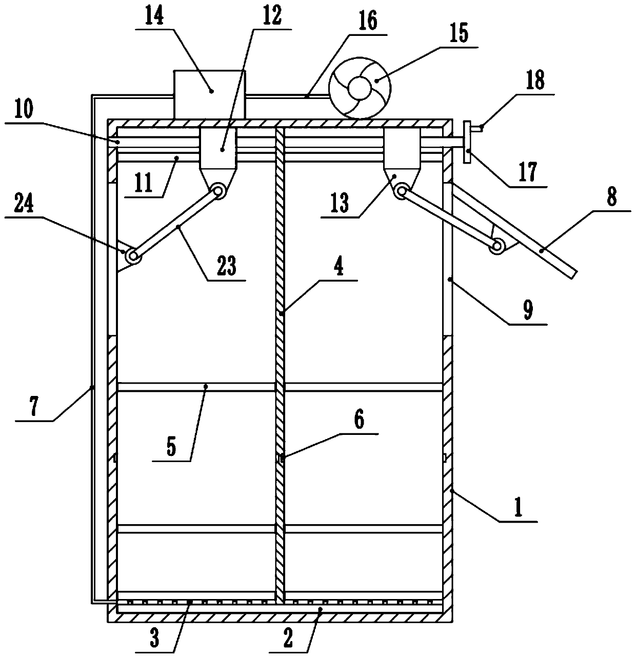
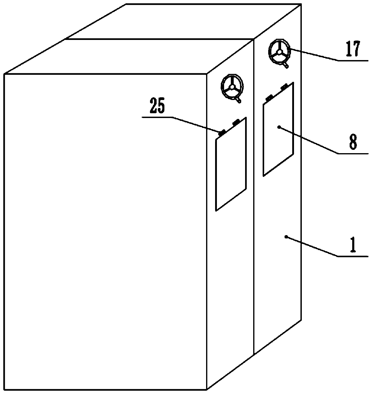
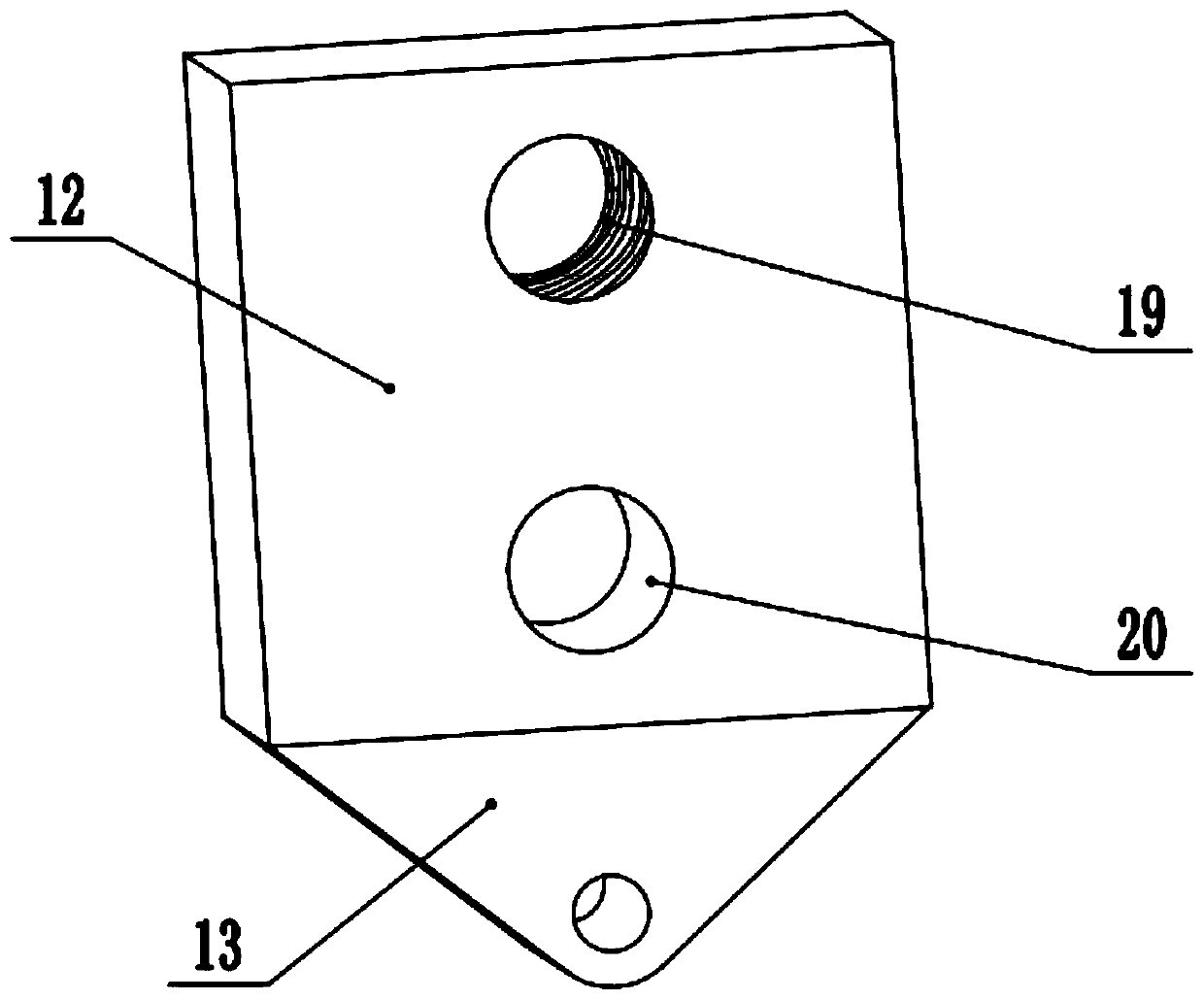
[0028] refer to Figure 1~4 , in an embodiment of the present invention, an adjustable moisture-proof compact shelf includes a cabinet body 1, a partition 4 is installed inside the cabinet body 1, and is used to divide the inside of the cabinet body 1, and the middle part of the upper end of the partition board 4 is installed with The rotating rod 10 is provided with a left-handed thread 21 in the middle part of the left end of the rotating rod 10, and a right-handed thread 22 is provided in the middle part of the right end of the rotating rod 10. When rotating, the moving block 12 can move in the opposite direction along the guide rod 11. One end of the rotating rod 10 passes through the cabinet body 1 and is connected with a drive disc 17. A drive handle 18 is installed in the middle of the drive disc 17 to drive the drive. The disk 17 rotates, and the middle part of both ends of the rotating rod 10 is equipped with a moving block 12, and the middle part of the upper end of ...

Embodiment 2

[0030] In another embodiment of the present invention, the difference between this embodiment and the above embodiment is that the inside of the drying box 14 is filled with a desiccant. By setting the desiccant and avoiding the use of electric heating wires in the form of electric heating, it can The gas with high humidity is physically dried, saving energy and realizing the drying function of the drying box 14 .

[0031] In the present invention, by placing the placement board 5 in the placement slots 6 of different heights inside the cabinet body 1, different types of articles are placed. When it is necessary to dry the articles inside the compact shelf, we can start the air intake 15. Through the drying function of the drying box 14, and the drying gas is introduced into the cabinet 1 through the air nozzle 3, so as to realize the moisture-proof effect of the internal items, and the rotating rod 10 can be rotated by rotating the driving handle 18 according to the external e...


PUM


Abstract

The invention discloses an adjustable dampproof compact rack, and belongs to the technical field of a compact rack. The adjustable dampproof compact rack comprises a cabinet body, wherein a separationplate is arranged inside the cabinet body; a rotating rod is arranged at the middle part of the upper end of the separation plate; moving blocks are arranged at the middle parts of two ends of the rotating rod; a guide block is arranged at the middle part of the lower end of each moving block; the lower end of each guide block is hinged to a pull rod through a fixing block; the bottom end of thepull rod is connected with a pull door through a hinging block; the top end of the pull door is connected with the cabinet body through a hinge; the separation plate is arranged in the cabinet body; aplurality of parallel placing grooves are respectively formed between the middle part of the separation plate and the inner wall of the cabinet body; placing plates are arranged inside the placing grooves; an air blowing cavity is arranged at the bottom end inside the cabinet body; the air blowing cavity is connected with a drying box through an air outlet pipe; the other end of the drying box isconnected with an air inlet machine through an air inlet pipe. Different height regulation can be realized on a space inside the cabinet body; the placement requirement of articles in different typesand sizes is met; meanwhile, through the matching of the installed drying box and the pull door, the dampproof performance inside the compact rack is ensured.

Description

technical field [0001] The invention relates to the technical field of compact shelves, in particular to an adjustable moisture-proof compact shelf. Background technique [0002] Compact shelf, also known as dense cabinet, is a kind of intensive file installation. It can be understood and defined in this way: it is a shelf that installs axle wheels on the base of the double-sided fixed frame of the double column, and can move linearly along the small guide rail laid on the ground. Move multiple shelves together or apart as needed. According to different operations, the compact racks are divided into: manual compact racks, electric compact racks, and electronic smart compact racks. According to different purposes, it is generally divided into: file racks, book racks, accounting racks, medical records racks, storage racks, etc. According to different structures, it can be divided into: open compact rack, semi-closed compact rack, and fully enclosed compact rack. [0003] At...

Claims


Application Information

Patent Timeline
IPC IPC(8): A47B53/02A47B63/00A47B57/08A47B97/00F26B21/00
CPCA47B53/02A47B57/08A47B63/00A47B97/00A47B2220/0002A47B2220/0091F26B21/00
Inventor 张良
Owner 江西金钱豹保险设备集团有限公司
Why Eureka
Try Eureka