Cloth placing frame

A technology for placing racks and fabrics, which is applied in thin material processing, winding strips, transportation and packaging, etc. It can solve the problems of inconvenient operation and inability to realize height adjustment, and achieves convenient loading and unloading maintenance, simple structure and low price Effect

Inactive Publication Date: 2019-07-02
NINGBO EASTSUN TEXTILES
View PDF0 Cites 0 Cited by
  • Summary
  • Abstract
  • Description
  • Claims
  • Application Information

AI Technical Summary

Problems solved by technology

[0002] In the garment factory, it is often necessary to cut the fabric or samples before making clothes. However, when cutting the fabric, it is first necessary to roll the fabric into a roll and place it on the support frame of the cutting platform. The height will be different. The cloth rack of the existing equipment is at a specified height, and the height cannot be adjusted, which makes the operation inconvenient

Method used


Image

  • Cloth placing frame
  • Cloth placing frame

Examples


Embodiment Construction

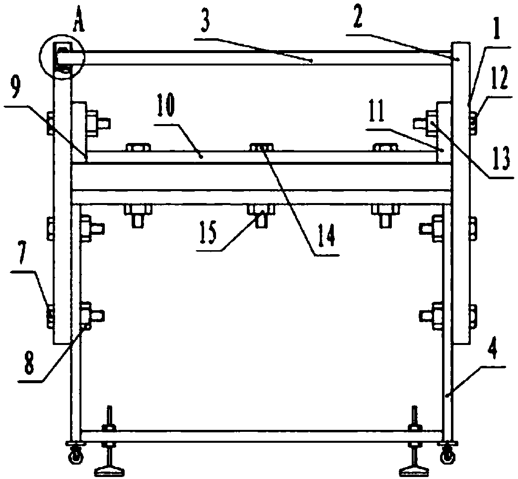
[0012] The specific implementation manners of the present invention will be further described in detail below in conjunction with the accompanying drawings and embodiments. The following examples are used to illustrate the present invention, but are not intended to limit the scope of the present invention.

[0013] Such as figure 1 As shown, a cloth placing frame includes two vertically placed support rods 1, and the two support rods 1 are fixedly connected to the right end support leg 4 of the cloth cutting platform 2 symmetrically front and back, and placed on the top of the two support rods 1 There is a detachable rotating shaft 3 for winding cloth, and a plurality of installation adjustment holes 16 are arranged on the outside evenly distributed vertically. The rotating shaft 3 can rotate around the axis. The distance between the adjustment holes 16 is the existing two rows of screws-7 and nuts. One-half of the installation distance of 8. The two support rods are fixedly...


PUM


Abstract

The invention provides a cloth placing frame. The cloth placing frame comprises two supporting rods which are vertically placed, wherein the two supporting rods are fixedly connected onto a right-endsupporting leg of a cloth cutting platform symmetrically front and rear; a separable rotary shaft for winding cloth is placed at the top ends of the two supporting rods; a plurality of mounting regulating holes which are vertically and uniformly distributed are formed in the outer sides of the two supporting rods; the rotary shaft can rotate around an axis; the two supporting rods are fixedly connected to a right-end supporting leg of the cloth cutting platform symmetrically front and rear; a separable rotary shaft for winding cloth is placed at the top ends of the two supporting rods; and a plurality of mounting regulating holes which are vertically and uniformly distributed are formed in the outer sides of the two supporting rods. The cloth placing frame is simple in structure, is low inprice, and is convenient in mounting and dismounting for maintenance.

Description

technical field [0001] The invention relates to a cloth placing rack. Background technique [0002] In the garment factory, it is often necessary to cut the fabric or samples before making clothes. However, when cutting the fabric, it is first necessary to roll the fabric into a roll and place it on the support frame of the cutting platform. The height will be different, and the cloth rack of the existing equipment is at a specified height, which cannot be adjusted in height, which makes the operation inconvenient. Contents of the invention [0003] (1) Technical problems to be solved [0004] The problem to be solved by the present invention is to provide a cloth placing rack, which has a simple structure, low price and convenient installation and maintenance. [0005] (2) Technical solution [0006] In order to solve the technical problem, the present invention provides a cloth placing frame, which includes two vertically placed support rods, and the two support rods ...

Claims


Application Information

Patent Timeline
Patent Type & Authority Applications(China)
IPC IPC(8): B65H16/06
CPCB65H16/06
Inventor 吴敏
Owner NINGBO EASTSUN TEXTILES
Why Eureka
Try Eureka