Angle measuring method in antenna field
A technology in the field of antennas, applied in radio wave measurement systems, radio wave reflection/re-radiation, measurement devices, etc., can solve the problems of inaccurate phase information, large amount of calculation, sudden change of measurement angle, etc., and achieve accurate phase information , reduce the amount of computation, and have excellent directional performance
- Summary
- Abstract
- Description
- Claims
- Application Information
AI Technical Summary
Problems solved by technology
Method used
Image
Examples
Embodiment 1
[0042] This embodiment provides an angle measurement method in the field of antennas, including:
[0043] S1: Calculate the phase difference between the antenna elements
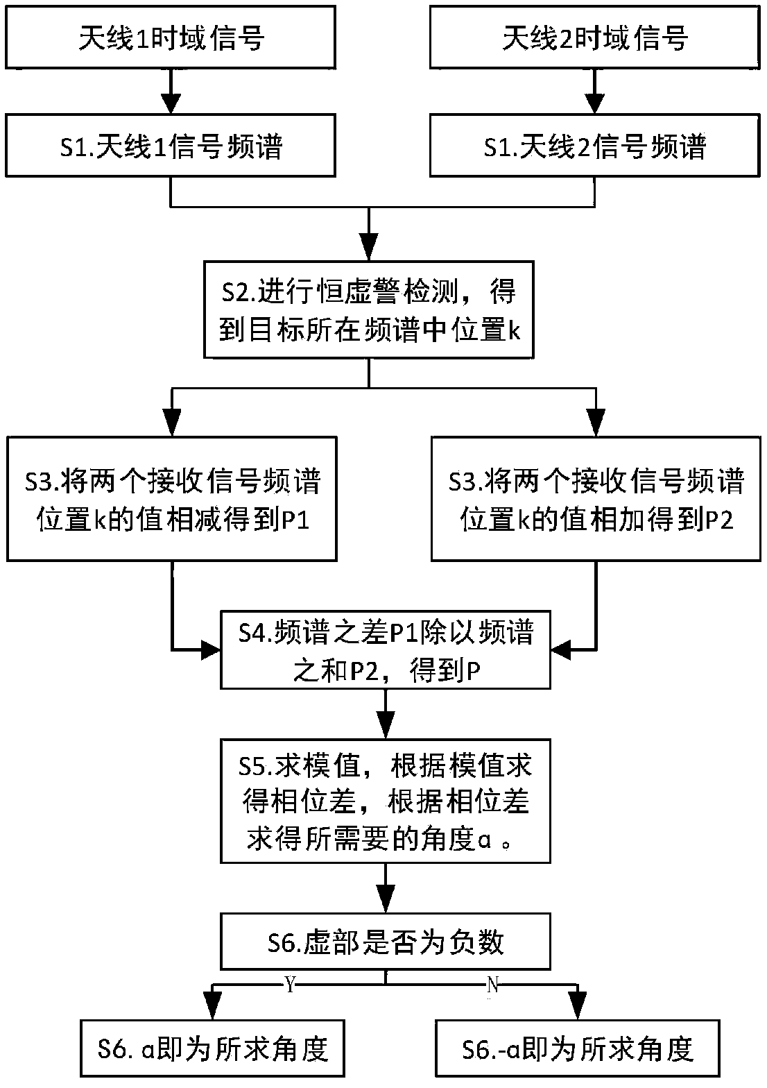
[0044] S2: Calculate the phase error signal P, and obtain the modulus value of the phase error signal P: details as follows:
[0045] Let the sum of the spectrum of the antenna be P1, and the difference of the spectrum be P2, the steps are as follows:
[0046] Sa. respectively performing FFT transformation on the time domain data received by the two antennas to obtain the signal spectrum;
[0047] Sb. Threshold detection is carried out to the spectrum information in Sa, and the position k in the spectrum where the target is obtained is obtained. When multiple targets are contained, k is an array;
[0048] Sc. adding and subtracting the value of position k in the frequency spectrum obtained in Sb, respectively, to obtain P1 and P2;
[0049] Sd. Divide P1 obtained in Sc by P2 to obtain the phase error s...
Embodiment 2
[0053] This embodiment provides another angle measurement method in the field of antennas, including:
[0054] S1: Calculate the phase difference between the antenna elements
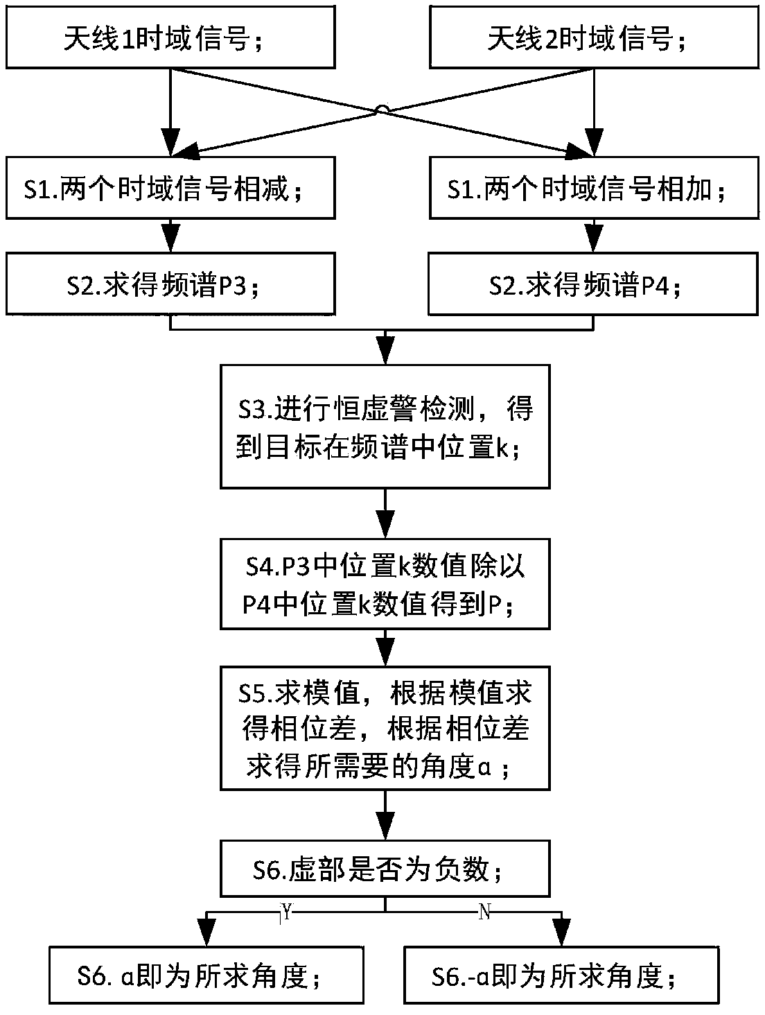
[0055] S2: Calculate the phase error signal P, and obtain the modulus value of the phase error signal P: details as follows:
[0056] SA. Adding and subtracting the time-domain data of the two receiving antennas respectively;
[0057] SB. performing FFT transformation on the time domain data obtained in SA respectively, to obtain spectrum P3 and spectrum P4;
[0058] SC. Carry out constant false alarm detection to the frequency spectrum P4 obtained by SB, and obtain the position k of the target in the frequency spectrum;
[0059] SD. respectively divide the values corresponding to position k of P3 and P4 obtained in SB to obtain the phase error signal P;
[0060] The above P1, P2, P3, P4, P are all imaginary numbers.
[0061] S3: According to the phase difference between antenna elements and...
Embodiment 3
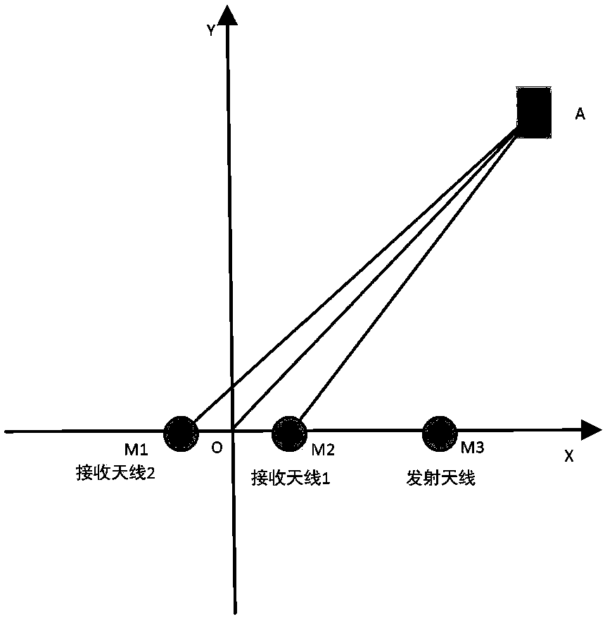
[0064] As a supplement to Embodiment 1 or 2: Assume that the time domain data of antenna I and antenna II are obtained by mixing the data obtained by the receiving antenna, and finally output the angle at which the target is located; let the distance between the two receiving antennas be d, the system The wavelength of the transmitted signal is λ, and the number of FFT transformation points is N_FFT, such as figure 1 As shown, d=M1M2 (representing the distance between M1 and M2, and so on), the angle of the target is α=∠AOY, the distance between the target and the receiving antenna 1 is R1=AM1, and the distance between the target and the receiving antenna 2 is R2 =AM2, the distance between the target and the center of the antenna is R=AO, then according to the law of cosines:
[0065]
[0066]Because d<
[0067]
[0068] Empathy
[0069]
[0070] The phase difference between the antenna ...
PUM
 Abstract
Description
Claims
Application Information
 - R&D
- Intellectual Property
- Life Sciences
- Materials
- Tech Scout
- Unparalleled Data Quality
- Higher Quality Content
- 60% Fewer Hallucinations
Browse by: Latest US Patents, China's latest patents, Technical Efficacy Thesaurus, Application Domain, Technology Topic, Popular Technical Reports.
© 2025 PatSnap. All rights reserved.Legal|Privacy policy|Modern Slavery Act Transparency Statement|Sitemap|About US| Contact US: help@patsnap.com


