Improved phase comparison angle measurement method
An angle measurement and phase comparison technology, applied in radio wave measurement systems, instruments, etc., can solve problems such as large computational load, inaccurate phase information, and sudden change in measured angle, and achieve reduced computational load, accurate phase information, and direction. Excellent performance
- Summary
- Abstract
- Description
- Claims
- Application Information
AI Technical Summary
Problems solved by technology
Method used
Image
Examples
Embodiment 1
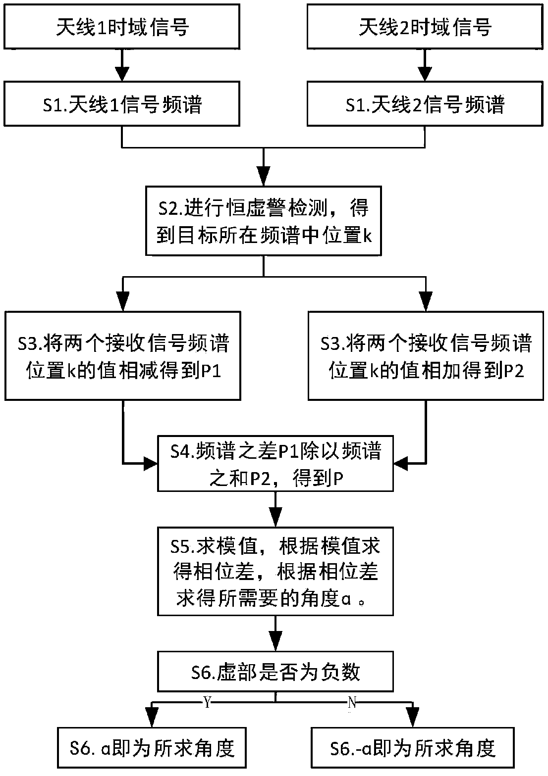
[0042] This embodiment provides an improved method for measuring angles by phase comparison, including:
[0043] S1: Calculate the phase difference between the antenna elements
[0044] S2: Calculate the phase error signal P, and obtain the modulus value of the phase error signal P: details as follows:
[0045] Let the sum of the spectrum of the antenna be P1, and the difference of the spectrum be P2, the steps are as follows:
[0046] Sa. respectively performing FFT transformation on the time domain data received by the two antennas to obtain the signal spectrum;
[0047] Sb. Threshold detection is carried out to the spectrum information in Sa, and the position k in the spectrum where the target is obtained is obtained. When multiple targets are contained, k is an array;
[0048] Sc. adding and subtracting the value of position k in the frequency spectrum obtained in Sb, respectively, to obtain P1 and P2;
[0049] Sd. Divide P1 obtained in Sc by P2 to obtain the phase ...
Embodiment 2
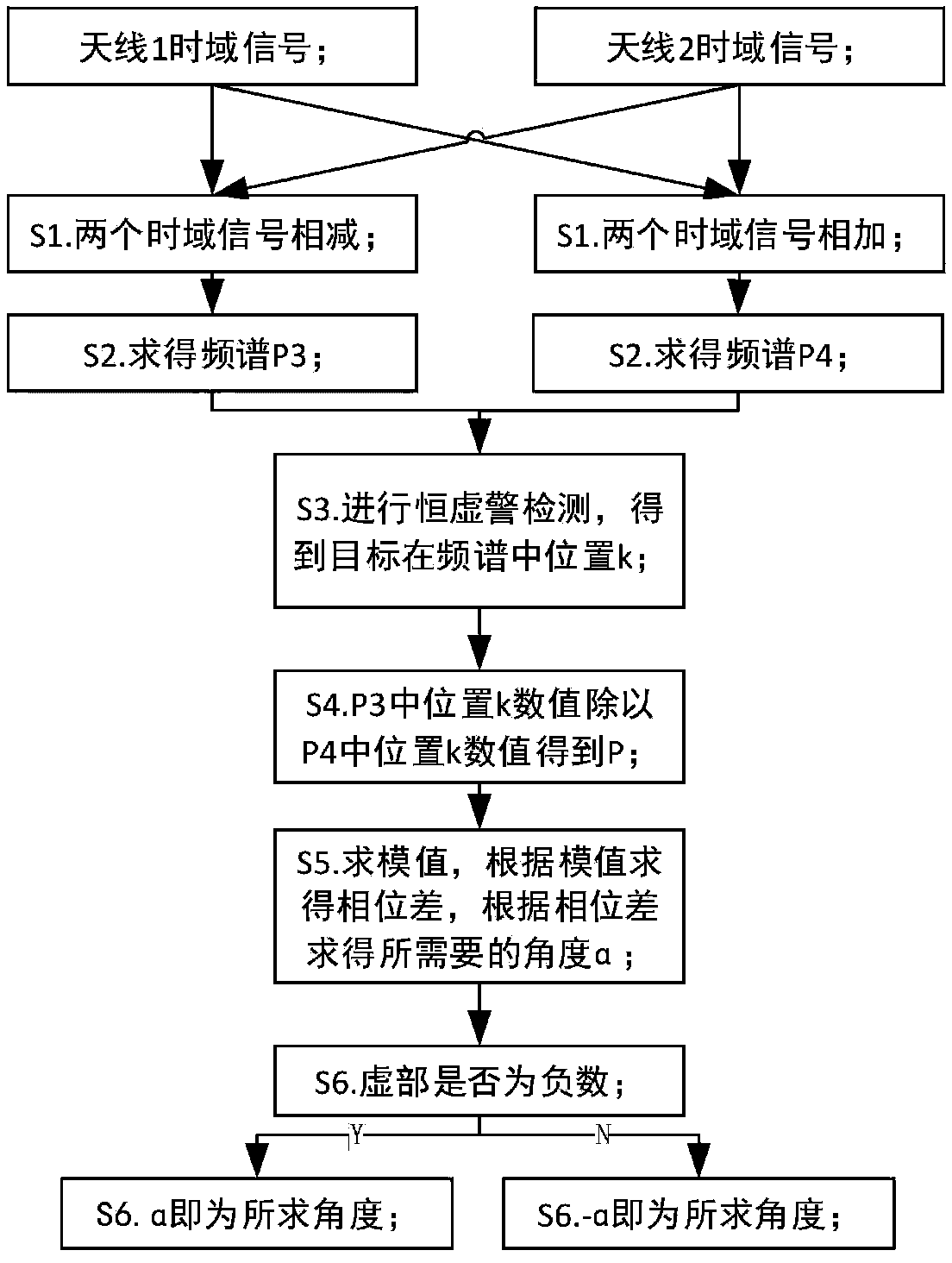
[0053] This embodiment provides another improved method for measuring angles by phase comparison, including:
[0054] S1: Calculate the phase difference between the antenna elements
[0055] S2: Calculate the phase error signal P, and obtain the modulus value of the phase error signal P: details as follows:
[0056] SA. Adding and subtracting the time-domain data of the two receiving antennas respectively;
[0057] SB. performing FFT transformation on the time domain data obtained in SA respectively, to obtain spectrum P3 and spectrum P4;
[0058] SC. Carry out constant false alarm detection to the frequency spectrum P4 obtained by SB, and obtain the position k of the target in the frequency spectrum;
[0059] SD. respectively divide the values corresponding to position k of P3 and P4 obtained in SB to obtain the phase error signal P;
[0060] The above P1, P2, P3, P4, P are all imaginary numbers.
[0061] S3: According to the phase difference between antenna element...
Embodiment 3
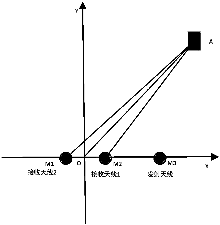
[0064] As a supplement to Embodiment 1 or 2: Assume that the time domain data of antenna I and antenna II are obtained by mixing the data obtained by the receiving antenna, and finally output the angle at which the target is located; let the distance between the two receiving antennas be d, the system The wavelength of the transmitted signal is λ, and the number of FFT transformation points is N_FFT, such as figure 1 As shown, d=M1M2 (representing the distance between M1 and M2, and so on), the angle of the target is α=∠AOY, the distance between the target and the receiving antenna 1 is R1=AM1, and the distance between the target and the receiving antenna 2 is R2 =AM2, the distance between the target and the center of the antenna is R=AO, then according to the law of cosines:
[0065]
[0066]Because d<
[0067]
[0068] Empathy
[0069]
[0070] The phase difference between the antenna ...
PUM
 Abstract
Description
Claims
Application Information
 - R&D
- Intellectual Property
- Life Sciences
- Materials
- Tech Scout
- Unparalleled Data Quality
- Higher Quality Content
- 60% Fewer Hallucinations
Browse by: Latest US Patents, China's latest patents, Technical Efficacy Thesaurus, Application Domain, Technology Topic, Popular Technical Reports.
© 2025 PatSnap. All rights reserved.Legal|Privacy policy|Modern Slavery Act Transparency Statement|Sitemap|About US| Contact US: help@patsnap.com


