Eureka AIR delivers breakthrough ideas for toughest innovation challenges, trusted by R&D personnel around the world.

Slurry vacuum defoaming machine

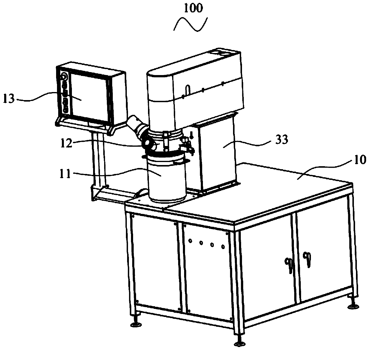
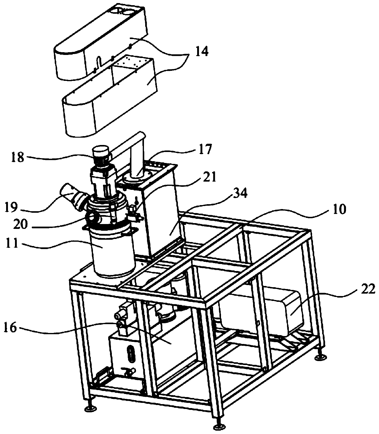
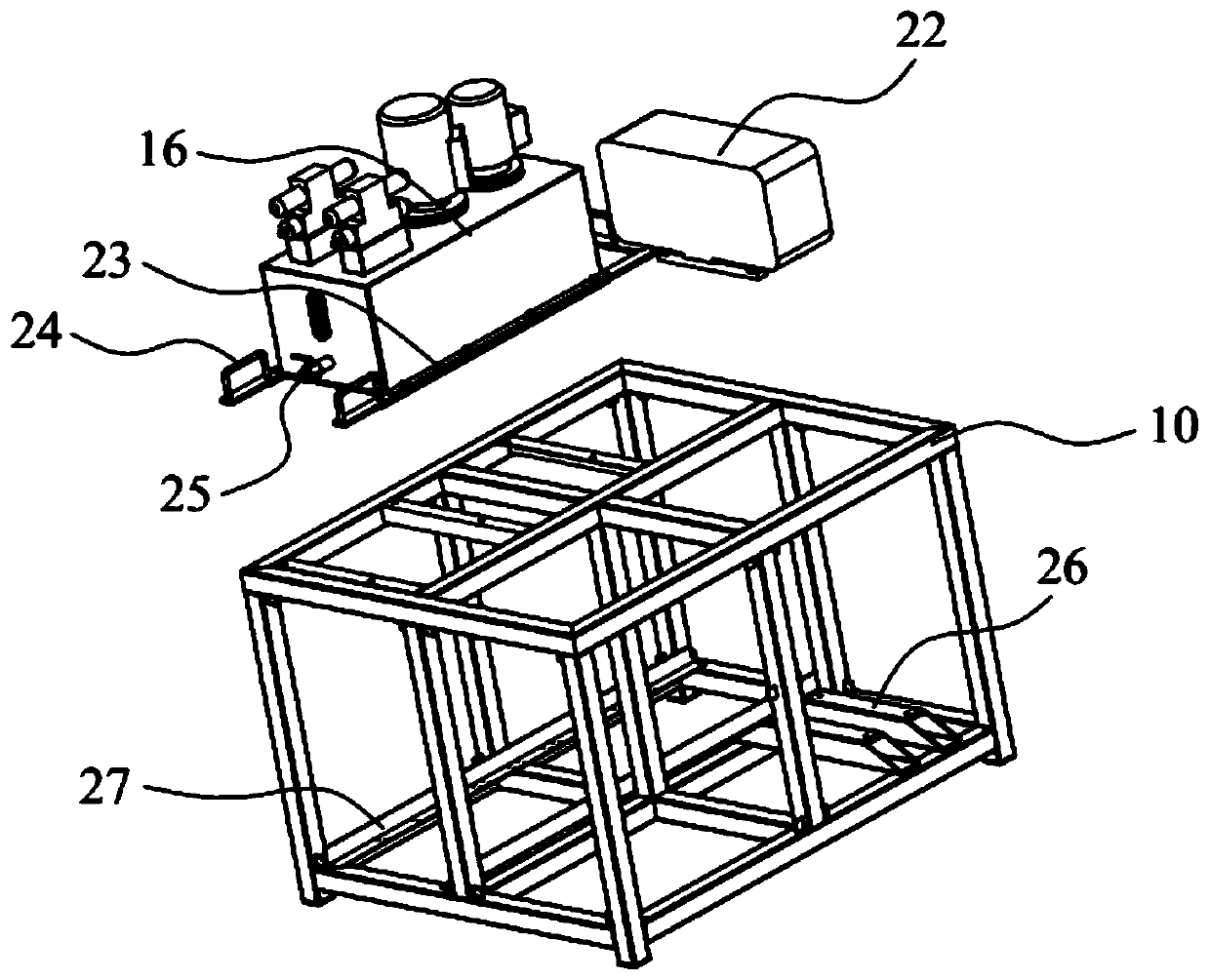
A vacuum degassing machine and slurry technology, which is applied in the direction of liquid degassing, liquid degassing adjustment/control, chemical instruments and methods, etc., can solve the problems of low stirring efficiency, improve stirring efficiency, and prevent slurry water loss , the effect of convenient operation

Inactive Publication Date: 2019-07-05
CHINA BANKNOTE PRINTING & MINTING +1
View PDF7 Cites 0 Cited by
  • Summary
  • Abstract
  • Description
  • Claims
  • Application Information

AI Technical Summary

Problems solved by technology

[0004] Based on this, the present invention provides a slurry vacuum degassing machine, which is used to solve the problem of low stirring efficiency in the prior art

Method used


Image

  • Slurry vacuum defoaming machine
  • Slurry vacuum defoaming machine
  • Slurry vacuum defoaming machine

Examples


Embodiment Construction

[0024] In order to make the purpose, technical solutions and advantages of the embodiments of the present invention clearer, the technical solutions in the embodiments of the present invention will be clearly and completely described below in conjunction with the accompanying drawings in the embodiments of the present invention. Obviously, the described embodiments It is some embodiments of the present invention, but not all of them. Based on the implementation manners in the present invention, all other implementation manners obtained by persons of ordinary skill in the art without creative efforts fall within the protection scope of the present invention. Accordingly, the following detailed description of the embodiments of the invention provided in the accompanying drawings is not intended to limit the scope of the claimed invention, but merely represents selected embodiments of the invention. Based on the implementation manners in the present invention, all other implement...


PUM


Abstract

The invention provides a slurry vacuum defoaming machine, which comprises a work bench, a stirring assembly, a defoaming assembly, and a driving assembly. The stirring assembly comprises a stirring head, a charging basket, stirring paddles, and a scraper blade. The stirring head comprises a decelerator, an adapter, and a planetary plate. The stirring paddles and the scraper plate are both connected to the planetary plate. The defoaming assembly comprises a vacuum pump, an air inlet adjuster, and a vacuum adjuster. The vacuum pump is communicated with the charging basket. The driving assembly comprises a hydraulic pump, a hydraulic cylinder and a hydraulic motor. The hydraulic pump is arranged in the work bench. The hydraulic cylinder is arranged on the work bench. The hydraulic motor is connected to the decelerator. Through the planetary plate, the stirring paddles, and the scraper plate, the slurry is stirred by dual speed variable stirring paddles and the scraper plate, the slurry stirring efficiency is effectively improved; through the air inlet adjuster and the vacuum adjuster, the vacuum degree of the interior of the charging basket can be effectively regulated; and water lossand agglomeration of slurry due to excessively large vacuum degree are prevented.

Description

technical field [0001] The invention relates to the technical field of defoaming machines, in particular to a slurry vacuum defoaming machine. Background technique [0002] Vacuum defoaming technology is widely used in the defoaming of food, chemical and other liquid slurries with air bubbles. In the process of making plastic layer slurry with wiper rolls of banknote printing companies, defoaming treatment is required so that there is no air bubbles in the coating and sizing process. Bubbles emerge to improve the quality of the wiping roller. Due to the high viscosity of the slurry, the adequacy of stirring and the high requirements for degassing, therefore, the degassing efficiency of the slurry vacuum degassing machine has attracted more and more attention. [0003] During the use of the existing slurry vacuum degassing machine, the stirring efficiency is low, which leads to insufficient stirring of the slurry, and the existing slurry vacuum degassing machine cannot effec...

Claims


Application Information

Patent Timeline
IPC IPC(8): B01D19/00
CPCB01D19/0052B01D19/0063B01D19/0073
Inventor 严建华李政安儒强周小龙罗宗平李桂华梁晓燕张旭刚陶华林林峰傅强杨传贵
Owner CHINA BANKNOTE PRINTING & MINTING
Why Eureka
Eureka Blog
Learn More