Jet stirrer

An agitator and jet technology, which is used in fluid mixers, mixers with rotary stirring devices, chemical instruments and methods, etc., to avoid frequent maintenance and facilitate installation and use.

Pending Publication Date: 2019-07-05
浙江长城搅拌设备股份有限公司
View PDF0 Cites 1 Cited by
  • Summary
  • Abstract
  • Description
  • Claims
  • Application Information

AI Technical Summary

Problems solved by technology

There is inevitably a sealing problem at the intersection of the transmission shaft and the kettle wall

Method used


Image

  • Jet stirrer
  • Jet stirrer
  • Jet stirrer

Examples


Embodiment Construction

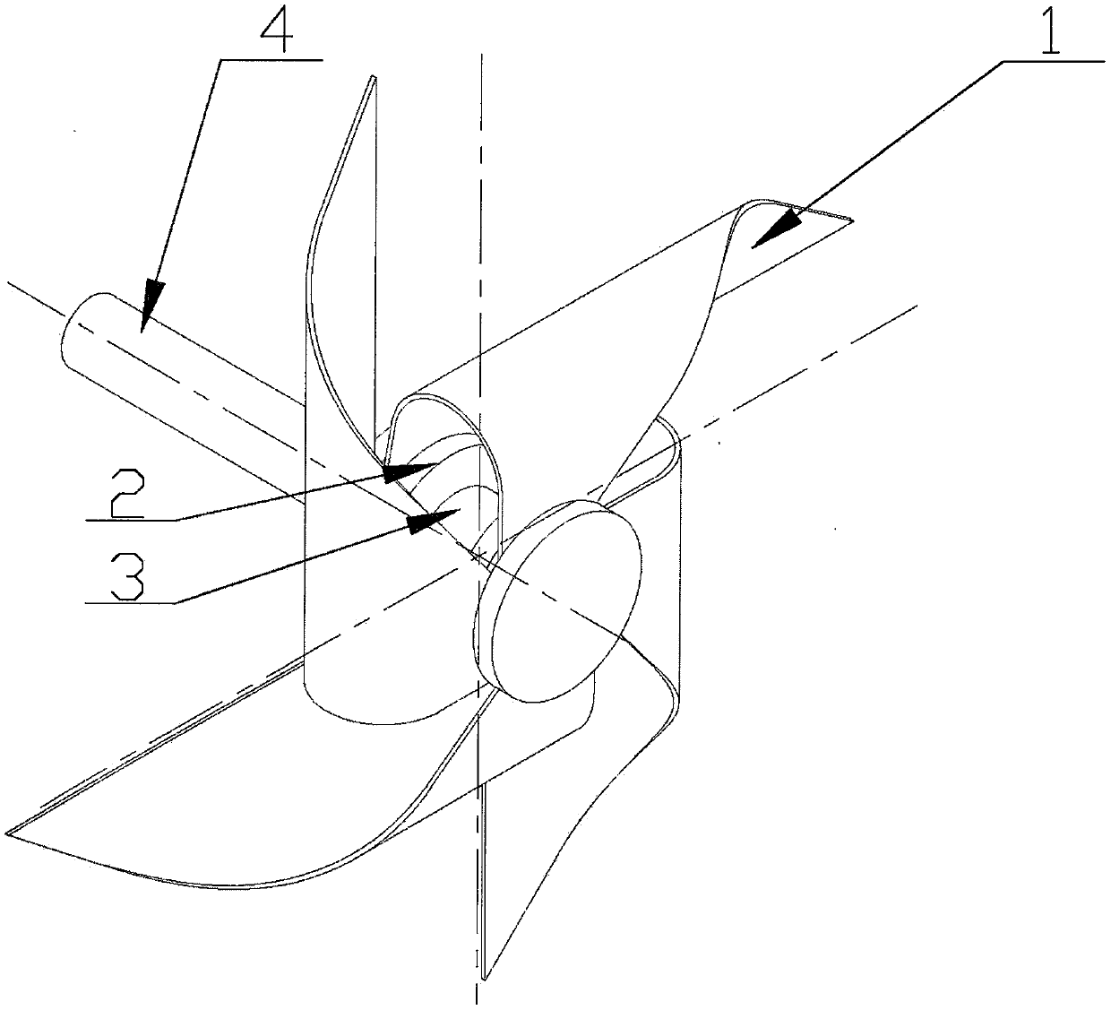
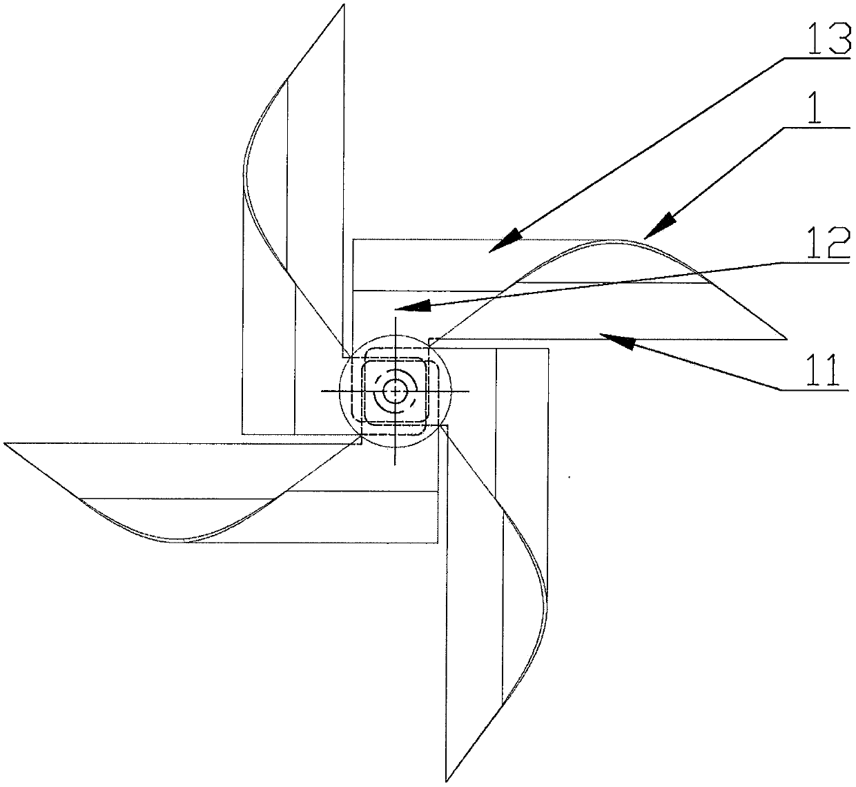
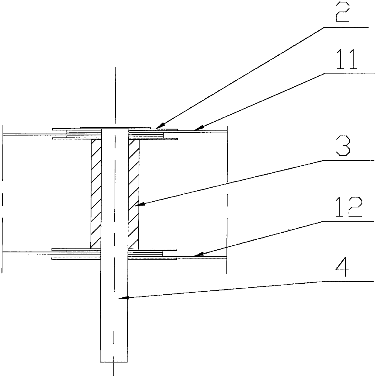
[0012] As an embodiment of the jet agitator, the jet agitator is located above the jet flow direction of the jet pipe 5 in the kettle, and is installed on the kettle wall 6 through the pin shaft 4 . The agitator includes an impeller 1, a splint 2 and a spacer 3. The impeller 1 includes a flat plate 11, a flat plate 12 and a curved plate 13 connecting them through one side. When the impeller 1 is installed on the pin shaft 4, the flat plate 11 at one end consists of two upper and lower The splint 2 is clamped and fixed, and the flat plate 12 at the other end is also clamped and fixed by the upper and lower two splints 2. The distance between the two ends is opened by the spacer 3. Four impellers 1 are used, and the outer edge is 45 degrees oblique, that is, The outer edge of the flat plate 11 and the flat plate 12 is 45 degrees to the radial direction, the surface where the outer edge of the curved panel 13 is located is 45 degrees to the pin axis, and the three sections of the ...


PUM


Abstract

The invention discloses a jet stirrer which is located in front of the jet direction of a jet pipe (5) in a kettle and installed on a kettle wall (6) through a pin shaft (4). The stirrer comprises animpeller (1), a clamping plate (2) and a separation sleeve (3). The outer edge of the impeller (1) is in a 45-degree slash shape. The jet stirrer has the advantages that the jet effect of the jet stirrer can be realized, the effect of changing the fluid direction through mechanical stirring can also be realized, fluid can be better mixed, energy can be sufficiently utilized when the rotary mixingof the jet stirrer is driven with the aid of jet, no leakage problem exists compared with a mechanical stirrer, installing and using are both quite convenient, and frequent maintenance is avoided.

Description

technical field [0001] The invention belongs to the technical field of stirring, in particular to a jet stirrer. Background technique [0002] Mechanical stirring equipment is widely used in various reaction processes. The working process of mechanical stirring equipment is to transmit the power of the driving device outside the kettle to the agitator on the stirring shaft inside the kettle through the transmission shaft, so as to realize the mixing of the fluid materials in the kettle. This inevitably has a sealing problem at the intersection of the transmission shaft and the wall of the kettle. If the working conditions of the equipment are high temperature and high pressure and no leakage is allowed, a mixing equipment with a jet mixer can be used. Contents of the invention [0003] The technical problem to be solved by the present invention is to provide a jet agitator, which is used in jet agitation equipment to achieve a good mixing effect on the materials in the ke...

Claims


Application Information

Patent Timeline
IPC IPC(8): B01F5/02B01F7/10B01F27/73
CPCB01F25/20B01F27/73
Inventor 谢明辉邹晨王洪群林鹏辉王炳信孟绳续荆万仓林苏奔
Owner 浙江长城搅拌设备股份有限公司
Why Eureka
Try Eureka