Automatic grout distributing device and grout distributing method for the bottom of ceramic tile adobe

A technology for ceramic bricks and bottom slurry, applied in the field of ceramic tile production, can solve the problems of easy deviation of the hollow soft rubber tube, damage to the performance and concentration of the bottom slurry, uneven bottom of the tile, etc., to control the thickness and uniformity of the slurry, The effect of high bottom slurry utilization and consistent bottom slurry performance

Active Publication Date: 2021-04-13
GUANGDONG JIA MEI CERAMIC +3
View PDF6 Cites 0 Cited by
  • Summary
  • Abstract
  • Description
  • Claims
  • Application Information

AI Technical Summary

Problems solved by technology

[0009] ⑴Because the hollow soft rubber tube is not fixed, it is easy to deviate, resulting in uneven bottom of the adobe during the grouting process;
[0010] (2) Due to the use of a single slurry tank for the bottom slurry, when adding the brick bottom slurry, it is easy to add the thick slurry first and then add tap water, resulting in the undesirable phenomenon of uneven thickness of the brick bottom slurry;
[0011] ⑶The control of the thickness of the base slurry is restricted by the adsorption capacity of the hollow soft rubber tube, and can only be adjusted through the concentration of the base slurry, which is a single method;
[0012] ⑷Because the temperature of the adobe is higher than the temperature of the bottom slurry, the temperature of the bottom slurry will increase during the long-term recycling process, thereby destroying the performance and concentration of the bottom slurry

Method used


Image

  • Automatic grout distributing device and grout distributing method for the bottom of ceramic tile adobe
  • Automatic grout distributing device and grout distributing method for the bottom of ceramic tile adobe
  • Automatic grout distributing device and grout distributing method for the bottom of ceramic tile adobe

Examples


Embodiment Construction

[0047] The present invention will be described in further detail below in conjunction with accompanying drawing:

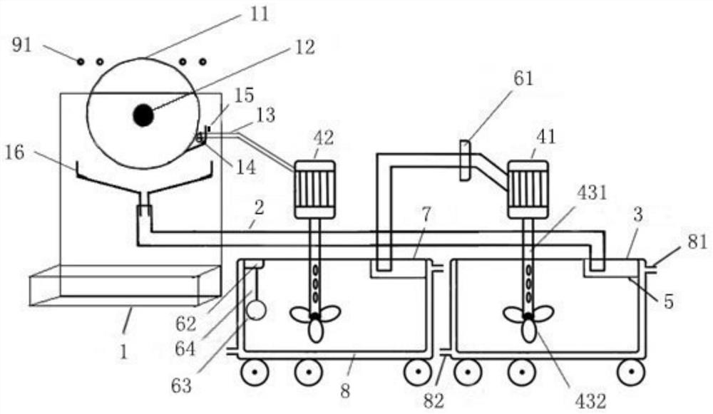
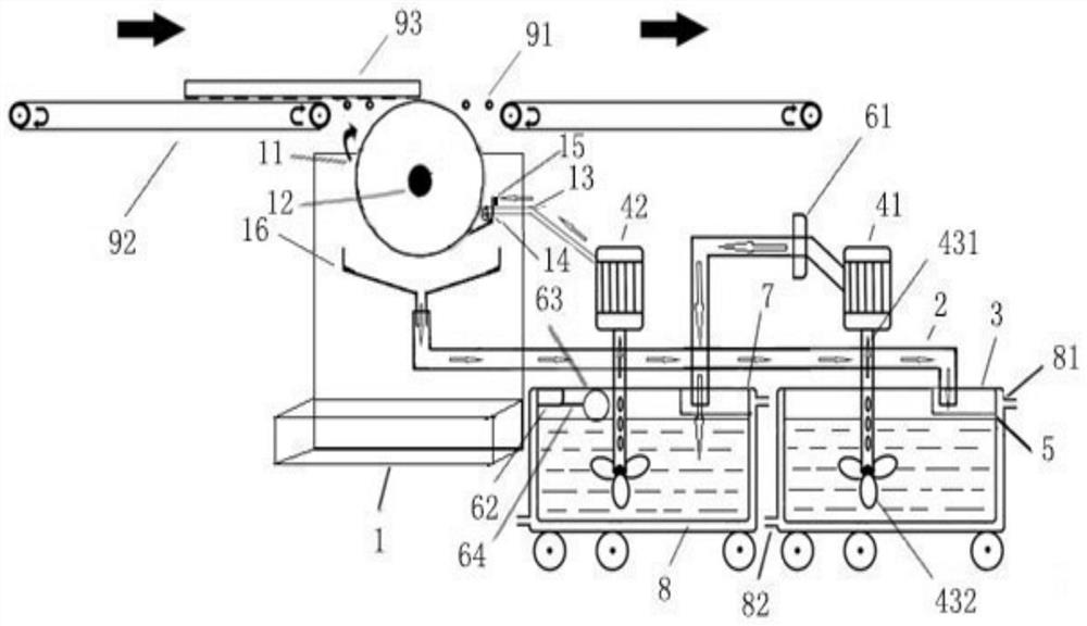
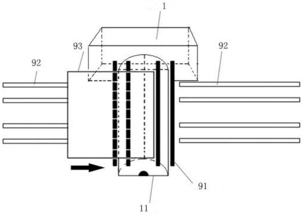
[0048] see figure 1 , image 3 As shown, the slurry distributing device is mainly composed of a transfer bottom slurry tank 3, a bottom slurry tank 7, a slurry return pipe 2, an automatic induction glazing device 71 (composed of an automatic induction valve 61, an inductor 62, and a suspension ball 63), a cooling Circulation system, rubber roller flower machine 1, rubber roller cylinder 11, support roller shaft 91, scraper 14 and primer tank 16 are composed.

[0049] The glaze of the transfer base tank 3 and the base tank 7 is made of stainless steel in the shape of a barrel. In particular, a set of cooling circulation system is installed on the outer wall of the transfer base tank 3 and base tank 7, and the temperature of the glaze slurry is controlled by cooling water circulation. Ensure the bottom slurry performance; the first bottom slurry pump 41 and the s...


PUM


Abstract

The invention relates to an automatic slurry distributing device and a slurry distributing method for the bottom of ceramic tiles. The device includes a brick conveying mechanism for the rubber roller flower machine to distribute the slurry, a primer tank and a transfer primer tank placed on the side of the rubber roller flower machine in sequence, and the rubber roller flower machine is connected to the second bottom tank installed in the primer tank through a sizing hose. There is a first primer pump in the transfer primer tank, and the glaze outlet pipe connected with the first primer pump extends into the primer tank. The primer tank and the transfer primer tank are equipped with a cooling circulation system. The flower machine is connected to the transfer bottom slurry tank through the slurry return pipe, and the excess bottom slurry is recovered into the transfer bottom slurry tank; the first bottom slurry pump and the second bottom slurry pump are both equipped with a slurry inlet pipe and a stirring tank located at the end of the slurry inlet pipe. mechanism. The base slurry of the present invention is evenly distributed on the bottom of the adobe through the rubber roller, and the uniform thickness of the slurry can be realized by adjusting the equipment, which can effectively prevent the base slurry from being easily precipitated and agglomerated and the concentration is unstable due to the temperature rise during the long-term circulation of the glaze slurry. , to prevent the uneven mixing of the original glaze and the recycled glaze slurry from affecting the uniform distribution of the slurry.

Description

technical field [0001] The invention relates to the field of ceramic tile production, in particular to an automatic slurry distributing device at the bottom of ceramic tile adobes and a slurry distributing method thereof. Background technique [0002] CN201620417238.9 discloses an automatic bottom pulping machine, including a slurry tank, a stirring shaft and a roller shaft are arranged in the slurry tank, and the stirring shaft and the roller shaft are respectively connected with a drive motor arranged outside the slurry tank, The roller shaft is set above the stirring shaft, the upper surface of the roller shaft is flush with the upper end of the slurry tank, the slurry tank is filled with slurry, and the slurry level of the slurry is higher than the lower surface of the roller shaft, and the stirring shaft is submerged In the slurry, the adobe passes through the roller, and the adobe dips the slurry on the surface of the roller to complete the step of applying the primer....

Claims


Application Information

Patent Timeline
Patent Type & Authority Patents(China)
IPC IPC(8): B28B11/04
CPCB28B11/046
Inventor 刘任松余恭勇林晓新班渊马占领陈振李俊章邓江文
Owner GUANGDONG JIA MEI CERAMIC
Why Eureka
Try Eureka