Y-shaped double valve sand discharger
A valve row and valve technology, which is applied in sea area engineering, construction, barrage/weir, etc., can solve the problems affecting the normal operation of the power generation system, affecting the flow of the main channel, and reducing the cleaning efficiency, and achieves simple structure, strong practicability, The effect of improving cleaning efficiency
- Summary
- Abstract
- Description
- Claims
- Application Information
AI Technical Summary
Problems solved by technology
Method used
Image
Examples
Embodiment 1
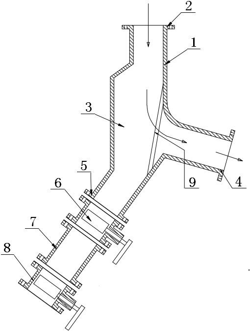
[0019] refer to figure 1 , a Y-shaped double-valve sand discharger, including a housing and a valve, the housing 1 is a Y-shaped three-channel structure with a slow flow chamber 3 inside, and the top end of the Y-shaped three-channel structure is provided with a first The flange 2 has a second flange 4 and a third flange 5 at its side and lower ends respectively, and the lower side of the third flange 5 is sequentially connected with a first valve 6, a sand storage pipe 7 and a second valve 8 ; The inner end of the channel connected to the second flange 4 is provided with a filter screen 9 . The sand storage pipe 7 is a circular pipe with flanges at both ends, and its diameter coincides with the diameters of the first valve 6 and the second valve 8 . The filter screen 9 is fixed by bolts. The first valve 6 and the second valve 8 are manual valves.
[0020] During installation and operation, the first valve 6 is set to be in an open state, and the second valve 8 is set to be...
Embodiment 2
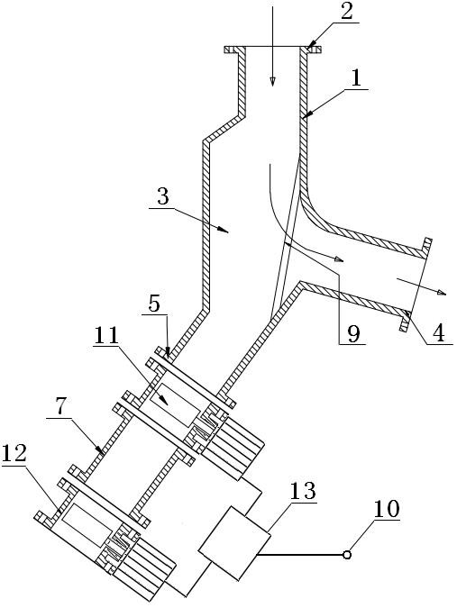
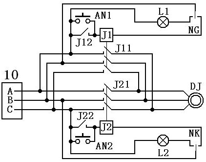
[0022] refer to figure 2 — image 3 , a Y-shaped double-valve sand discharger, including a housing and a valve, the housing 1 is a Y-shaped three-channel structure with a slow flow chamber 3 inside, and the top end of the Y-shaped three-channel structure is provided with a first The flange 2 has a second flange 4 and a third flange 5 at its side and lower ends respectively, and the lower side of the third flange 5 is sequentially connected with a first valve 11, a sand storage pipe 7 and a second valve 12 ; The inner end of the channel connected to the second flange 4 is provided with a filter screen 9 . The sand storage pipe 7 is a round pipe with flanges at both ends, and its diameter coincides with the diameters of the first valve 11 and the second valve 12 . The filter screen 9 is fixed by bolts. The first valve 11 and the second valve 12 are electric valves, and the two electric valves are controlled by a connected controller 13 , and the controller 13 is provided wit...
Embodiment 3
[0027] In this embodiment, on the basis of Embodiment 2, a timing circuit is added in the controller 13, referring to Figure 4 , the timing circuit includes a timer, a timing module and a regulated power supply, the input end of the timer DSQ is connected to the AC power supply, the output end is connected to the input end of the regulated power supply DC, and the positive output ends of the regulated power supply DC are respectively connected to the first The positive terminal of the power supply of the timing module K1, the positive terminal of the power supply of the second timing module K2, the positive terminal of the power supply of the third timing module K3 and the positive terminal of the power supply of the fourth timing module K4, the negative output terminal of the stabilized power supply DC is connected to the first timing The negative terminal of the power supply of the module K1, the negative terminal of the power supply of the second timing module K2, the negat...
PUM
 Abstract
Description
Claims
Application Information
 - R&D
- Intellectual Property
- Life Sciences
- Materials
- Tech Scout
- Unparalleled Data Quality
- Higher Quality Content
- 60% Fewer Hallucinations
Browse by: Latest US Patents, China's latest patents, Technical Efficacy Thesaurus, Application Domain, Technology Topic, Popular Technical Reports.
© 2025 PatSnap. All rights reserved.Legal|Privacy policy|Modern Slavery Act Transparency Statement|Sitemap|About US| Contact US: help@patsnap.com


