
Variable-cycle engine injector valve driving mechanism

A variable-cycle engine and drive mechanism technology, applied to machines/engines, jet propulsion devices, etc., can solve the problems of valve wear, structural parts stuck, complex valve trajectory, etc., to achieve good reliability and avoid circumferential gaps. The effect of uniform and simple motion trajectory

Active Publication Date: 2019-07-05
AECC SHENYANG ENGINE RES INST
View PDF7 Cites 3 Cited by
  • Summary
  • Abstract
  • Description
  • Claims
  • Application Information

AI Technical Summary

Problems solved by technology

[0003] In the prior art, the reciprocating motion of the actuator is converted into the translational motion of the ring valve through the crank or rocker structure, and the circumferential rotation of the valve is added at the same time. However, the valve movement trajectory is complicated, and the circumferential gap between the valve and the casing is uneven. It is easy to cause structural parts to stick and valves to wear

Method used


Image

  • Variable-cycle engine injector valve driving mechanism
  • Variable-cycle engine injector valve driving mechanism
  • Variable-cycle engine injector valve driving mechanism

Examples


Embodiment Construction

[0028] In order to make the purpose, technical solution and advantages of the application more clear, the technical solution in the embodiment of the application will be described in more detail below in conjunction with the drawings in the embodiment of the application. In the drawings, the same or similar reference numerals denote the same or similar elements or elements having the same or similar functions throughout. The described embodiments are some, but not all, embodiments of the application. The embodiments described below by referring to the figures are exemplary, and are intended to explain the present application, and should not be construed as limiting the present application. Based on the embodiments in this application, all other embodiments obtained by persons of ordinary skill in the art without creative efforts fall within the protection scope of this application. Embodiments of the present application will be described in detail below in conjunction with th...


PUM


Abstract

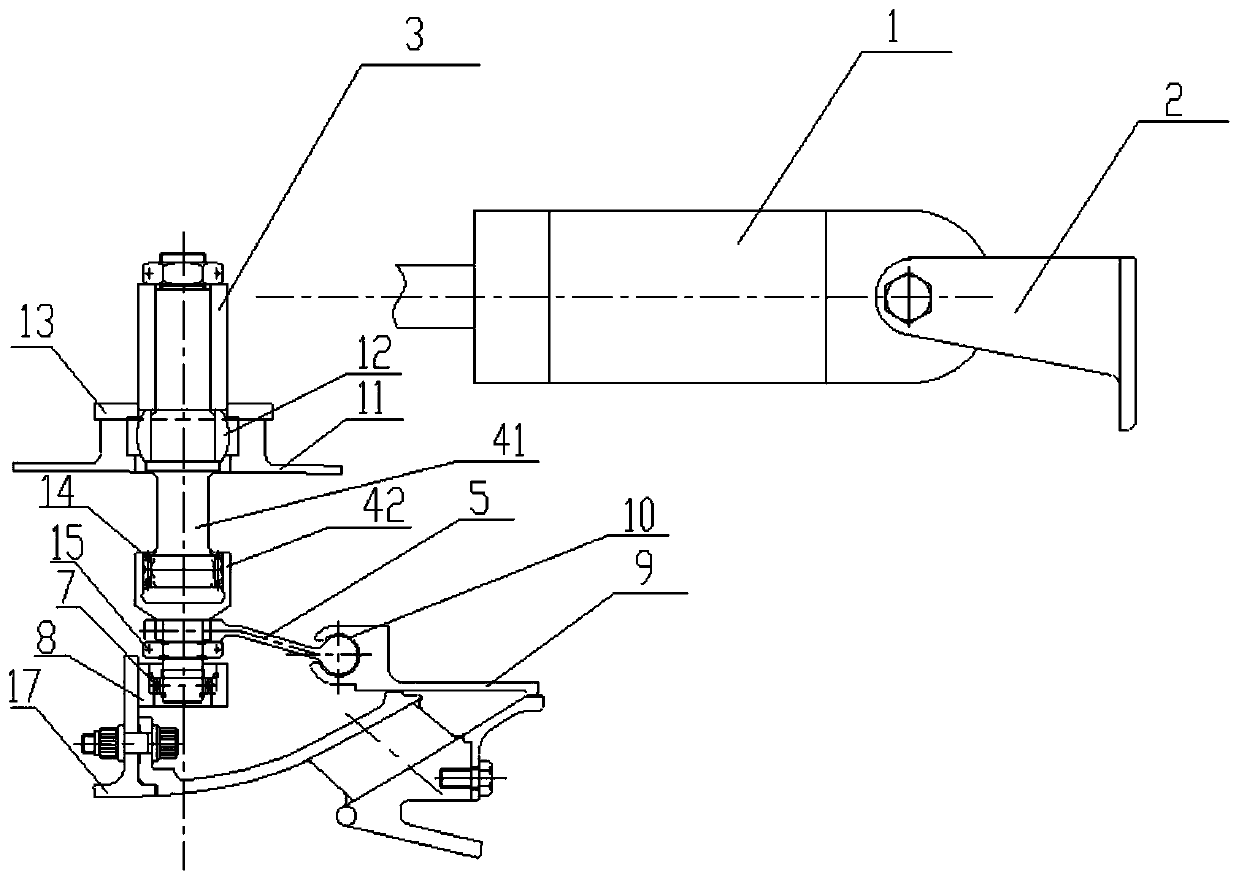
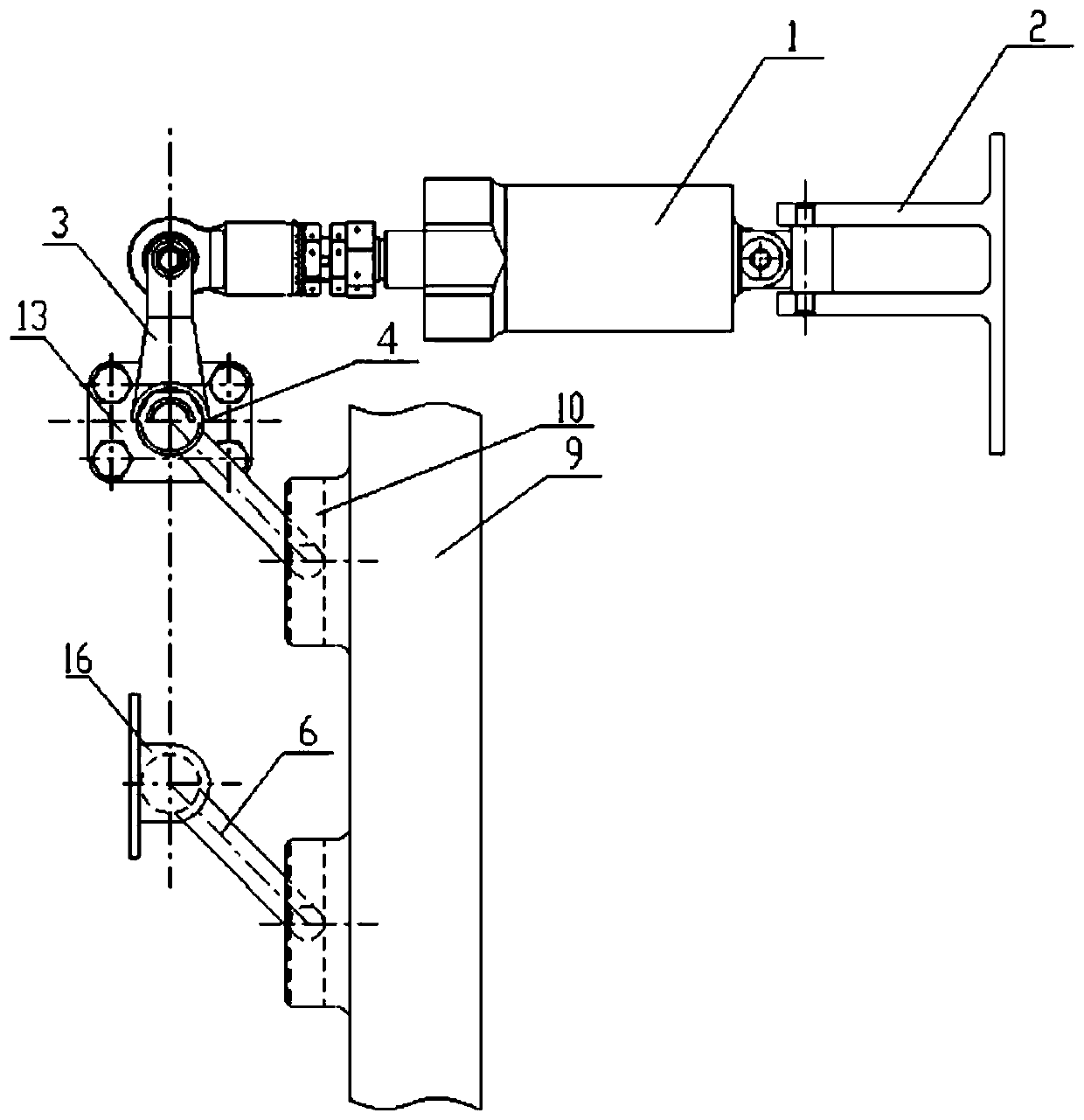
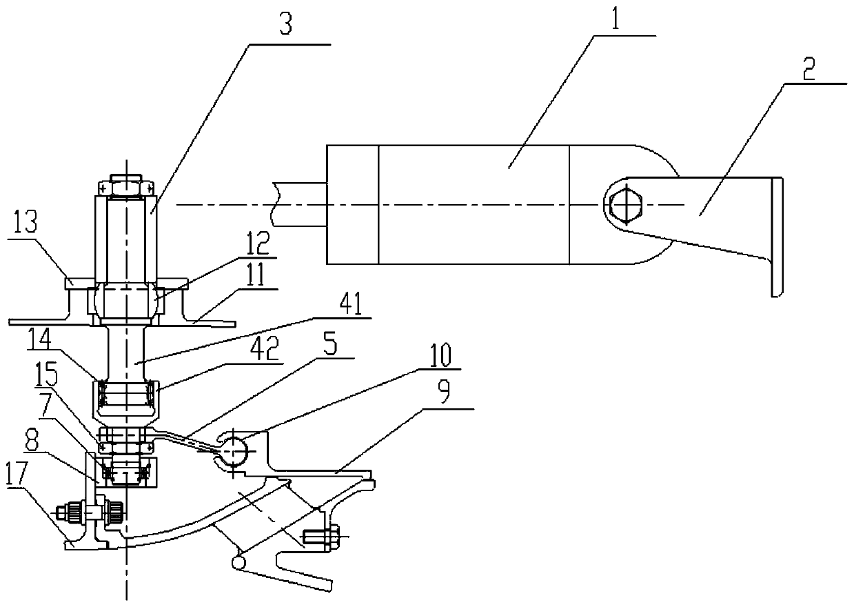
The invention belongs to the field of aero-engines, and particularly relates to a variable-cycle engine injector valve driving mechanism. The driving mechanism comprises an annular injector valve, anactuator, transmission rods, an inner-end driving rocker arm and an inner-end driven rocker arm; the annular injector valve is provided with a rocker arm slideway, one end of the actuator is connectedwith a support, and the other end of the actuator is connected with an outer transmission rocker arm; the transmission rods comprise the outer transmission rod and the inner transmission rod, one endof the outer transmission rod is connected with the outer transmission rocker arm, the middle of the outer transmission rod is rotationally arranged on a bypass duct casing, the other end of the outer transmission rod is connected with one end of the inner transmission rod through a spline, and the other end of the inner transmission rod is rotationally arranged on a core driven fan stage casing;one end of the inner-end driving rocker arm is fixedly connected with the inner transmission rod, and the other end of the inner-end driving rocker arm is arranged in the rocker arm slideway througha spherical structure; and one end of the inner-end driven rocker arm is fixed on the core driven fan stage casing, and the other end of the inner-end driven rocker arm is arranged in the rocker arm slideway through a spherical structure.

Description

technical field [0001] The application belongs to the field of aero-engines, and in particular relates to a variable-cycle engine injector valve driving mechanism. Background technique [0002] The variable cycle engine adjusts the thermodynamic cycle parameters in combination with changes in the geometric shape, size or position of some components. Compared with the conventional mixed displacement turbofan engine, the variable cycle engine has better flow matching performance with the intake port, reducing the conventional mixed displacement turbofan. The overflow resistance and rear body resistance that occur during the throttling process of the engine improve the flow capacity of the fan, thereby reducing the installation loss of the propulsion system. The Front Variable Area Bypass Inject (FVABI for short) is one of the variable geometry features of the variable cycle engine. [0003] In the prior art, the reciprocating motion of the actuator is converted into the trans...

Claims


Application Information

Patent Timeline
Patent Type & Authority Applications(China)
IPC IPC(8): F02K1/28
CPCF02K1/28
Inventor 纪福森姜永强张德志孙莹赵鑫
Owner AECC SHENYANG ENGINE RES INST
Learn More