Multi-wing centrifugal fan blade, vane wheel and multi-wing centrifugal fan

A centrifugal fan and airfoil blade technology, which is applied in the directions of machines/engines, mechanical equipment, liquid fuel engines, etc., can solve the problems of small inlet impact loss, small separation loss of blade trailing edge, no small bending angle, etc., and achieve excellent aerodynamics. performance, the effect of reducing inlet impact loss and blade trailing edge separation loss

Active Publication Date: 2019-07-05
FANS TECH ELECTRIC CO LTD
View PDF12 Cites 0 Cited by
  • Summary
  • Abstract
  • Description
  • Claims
  • Application Information

AI Technical Summary

Problems solved by technology

[0005] In view of this, the application provides a multi-blade centrifugal fan blade, impeller and a multi-blade centrifugal fan, which solve the existing technical problems of blades with small bending angles, small inlet impact losses and small separation losses of blade trailing edges

Method used


Image

  • Multi-wing centrifugal fan blade, vane wheel and multi-wing centrifugal fan
  • Multi-wing centrifugal fan blade, vane wheel and multi-wing centrifugal fan
  • Multi-wing centrifugal fan blade, vane wheel and multi-wing centrifugal fan

Examples


no. 1 example

[0034] The above is the first embodiment of a multi-blade centrifugal fan blade provided by the embodiment of the present application, and the following is the second embodiment of a multi-blade centrifugal fan blade provided by the embodiment of the present application.

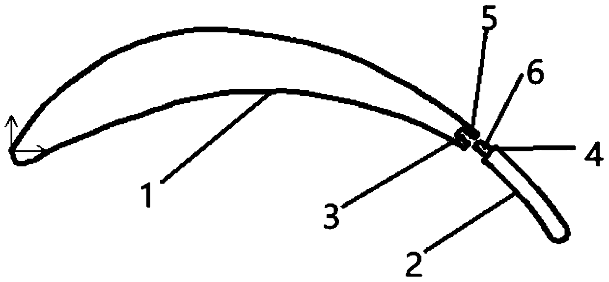
[0035] see figure 1 , a structural schematic diagram of a multi-blade centrifugal fan blade in an embodiment of the present application, including: an airfoil blade part 1 and an arc-shaped blade part 2; the tail end 3 of the airfoil blade part and the head end 4 of the arc-shaped blade part connect.

[0036] In order to make the performance of the blade better, the length d of the arc-shaped blade part 2 should not be too long, and the length d of the arc-shaped blade part 2 and the length D of the airfoil blade part 1 have the following relationship: h for

[0037] Further, h is specifically

[0038] Further, the airfoil blade part 1 and the arc-shaped blade part 2 are integrally formed.

[0039] ...


PUM


Abstract

The application discloses a multi-wing centrifugal fan blade, a vane wheel and a multi-wing centrifugal fan. The multi-wing centrifugal fan blade comprises a wing-shaped blade part and an arc-shaped blade part, wherein the tail end of the wing-shaped blade part is connected with the head end of the arc-shaped blade part. According to the multi-wing centrifugal fan blade disclosed by the application, the multi-wing centrifugal fan blade comprises the wing-shaped blade part and the arc-shaped blade part, the angle of an exit and entrance of the blade can be freely regulated through regulating the arc-shaped blade part, and the wing-shaped blade part adopts an optimal bending angle design, so that the bending angle of the blade cannot be too large; and through the wing-shaped blade part, theinlet impact loss of the arc-shaped blade part and the separation loss of a tail edge of the blade can be reduced, so that the inlet impact loss of the whole blade and the separation loss of the tailedge of the blade are reduced, the blade meets the optimal pneumatic performance, and the problem that in the prior art, the blade which is small in bending angle, low in inlet impact loss and low inseparation loss of the tail edge of the blade is not generated is solved.

Description

technical field [0001] The application belongs to the technical field of fans, and in particular relates to a multi-blade centrifugal fan blade, an impeller and a multi-blade centrifugal fan. Background technique [0002] The blade angle at the inlet and outlet of the multi-blade centrifugal fan has a great influence on the performance of the fan. The impeller of the existing multi-blade centrifugal fan mostly adopts the design of equal-thickness circular arc blade. This method can adjust the angle of the inlet and outlet blades arbitrarily to meet the aerodynamic performance of different fans. . [0003] However, the equal-thickness arc blade has the disadvantages of large airflow impact loss at the inlet and severe separation loss of the blade trailing edge, which makes it difficult to obtain better aerodynamic performance. The airfoil blade structure can reduce the impact loss of the airflow at the inlet and the separation loss of the blade trailing edge, and its aerodyn...

Claims


Application Information

Patent Timeline
IPC IPC(8): F04D29/30F04D29/28
CPCF04D29/283F04D29/30
Inventor 贾海军陈宗华
Owner FANS TECH ELECTRIC CO LTD
Why Eureka
Try Eureka