
Abradable coating for rotating blades of a turbomachine

Active Publication Date: 2022-06-14
SN DETUDE & DE CONSTR DE MOTEURS DAVIATION S N E C M A
View PDF34 Cites 0 Cited by
  • Summary
  • Abstract
  • Description
  • Claims
  • Application Information

AI Technical Summary

Benefits of technology

The abridable material described in this patent allows for the creation of an abridable coating that has good aerodynamic performance and is long-lasting. This means that it can withstand more wear and tear than existing abridable materials.

Problems solved by technology

However, the abradable nature of these materials which are capable of withstanding the conditions of use of the high-pressure turbines is very low.
However, on the one hand, the current methods for obtaining the abradable material coating and, on the other hand, the resistance to erosion of said abradable material coating caused by the circulation of abrasive particles, impose a void ratio of the abradable material less than 30%, thus limiting the abradable nature of the existing abradable materials.
However, progress in the management of efficiency and fuel consumption leads to an increase in the operating temperatures, particularly for the stages of the high-pressure turbine located directly downstream of the combustion chamber, as well as to a reduction in the clearance between the rotating blades and the casing.

Method used


Image

  • Abradable coating for rotating blades of a turbomachine
  • Abradable coating for rotating blades of a turbomachine

Examples


first embodiment

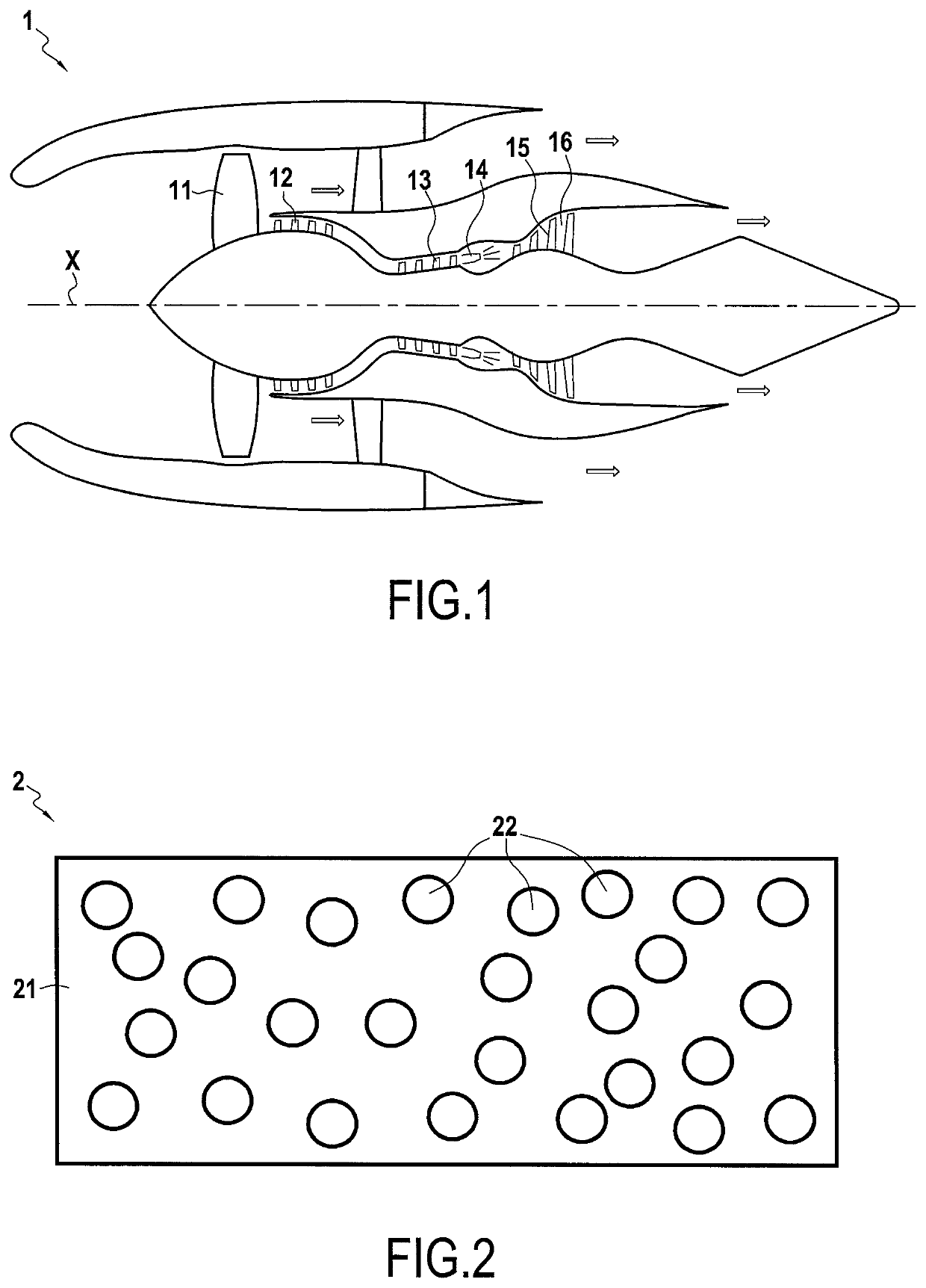
[0054] the matrix 21 is made of a first ceramic material, and the particles 22 are in a first ceramic material.

[0055]The first ceramic material has a dynamic viscosity greater than or equal to 1012 Pa·s at 1300° C., while the second ceramic material has a dynamic viscosity less than or equal to 102 Pa·s at 1300° C.

[0056]The dynamic viscosity is here measured with a Brookfield RVT viscometer equipped with a rotating mobile at 20 rpm or by a flow measurement.

[0057]The fact that the first ceramic material, for example, has a dynamic viscosity greater than 1012 Pa·s at 1300° C. allows the matrix 21 to maintain its mechanical properties, and thus allows the abradable coating 2 to withstand the very high temperature.

[0058]The fact that the second ceramic material has a dynamic viscosity less than or equal to 102 Pa·s at 1300° C. allows sufficiently weakening the matrix 21.

[0059]In addition, such a low viscosity of the second material allows the friction of the tip of the blading to smooth...

second embodiment

[0066] the matrix 21 is made of a first metal material, and the particles 22 are made of a second metal material.

[0067]The first metal material composing the matrix 21 has a melting temperature greater than 900° C., and preferably greater than 1000° C., and even more preferably greater than 1100° C., so as to maintain good mechanical properties and ensure the resistance of the abradable coating 2 at such temperatures.

[0068]The second metal material composing the particles 22 has, for its part, a melting temperature at least 50° C. less than the melting temperature of the first metal material.

[0069]Such a difference in melting temperature allows the particles 22 to switch into the liquid state upon contact between the tip of a blading and the abradable coating 2 under the effect of the increase in temperature, thus weakening the matrix 21 which remained solid.

[0070]Preferably, the second metal material has a melting temperature 50° C. to 200° C. lower than the melting temperature of ...


PUM

PropertyMeasurementUnit
Temperatureaaaaaaaaaa
Fractionaaaaaaaaaa
Fractionaaaaaaaaaa

Abstract

An abradable coating includes a matrix and particles that are dispersed in the matrix, the particles being made of a material switching into a fluid phase under the effect of the increase in temperature upon contact between a tip of a blading and the abradable coating.

Description

CROSS-REFERENCE TO RELATED APPLICATIONS[0001]This application is the U.S. National Stage of PCT / FR2019 / 051943, filed Aug. 20, 2019, which in turn claims priority to French patent application number 1857581 filed Aug. 22, 2018. The content of these applications are incorporated herein by reference in their entireties.BACKGROUND OF THE INVENTION[0002]The present invention relates to the general field of abradable material coatings for turbomachines, and particularly for aircraft engines.[0003]In order to ensure an aerodynamic sealing between the tip of rotating blades and the casing surrounding said rotating blades, it is known practice to deposit an abradable coating by applying on the internal contour of the casing a layer made of abradable material forming a track for the path from the tip of the blades along the casing.[0004]By “abradable” is meant here that the material is intended to wear out by abrasion upon contact with the blades. The abradable coating is eroded by the passag...

Claims


Application Information

Patent Timeline
IPC IPC(8): F01D11/12C23C4/073C23C4/11
CPCF01D11/122C23C4/073C23C4/11F05D2300/611C23C30/00F05D2300/6033F05D2300/6032
Inventor LE BIEZ, PHILIPPE CHARLES ALAINDROZ, NICOLASPIN, LISASELEZNEFF, SERGE GEORGES VLADIMIR
Owner SN DETUDE & DE CONSTR DE MOTEURS DAVIATION S N E C M A
Learn More