Method for unfolding and locking small-caliber projectile body-large wingspan space folding empennage

A small-caliber, tail fin technology, applied in the direction of offensive equipment, projectiles, weapon types, etc., can solve the problems of small deployment torque, inconvenient use of large torsion springs, complex structure, etc., to achieve reliable locking and self-locking, prevent back and forth swing, The effect of improving stability

Pending Publication Date: 2022-05-13
西安现代控制技术研究所
View PDF0 Cites 0 Cited by
  • Summary
  • Abstract
  • Description
  • Claims
  • Application Information

AI Technical Summary

Problems solved by technology

But they each have some defects and limitations: the moment generated by the torsion spring in the mode (1) acts directly on the empennage shaft, and the resulting deployment moment is relatively small, and due to the structural size limitation, it is not convenient to use a large torsion spring near the pivot ; Mode (2) has similar defects and limitations with mode (1), and the deployment moment produced is small; the deployment torque produced by mode (3) is large, but involves gas sealing and linkage design, complex structure, and structural not compact
[0004] The locking mechanism of the folding tail generally adopts round pin locking, lock key, limit block and other methods. The round pin lock method has a large amount of front and rear swing of the tail; the structure of the lock key and limit block is more complicated, and it is difficult to be built in. In the internal structure of the tail
[0005] For small-caliber projectiles, it is more difficult to meet the requirements of overall large aspect ratio by lateral folding

Method used


Image

  • Method for unfolding and locking small-caliber projectile body-large wingspan space folding empennage
  • Method for unfolding and locking small-caliber projectile body-large wingspan space folding empennage
  • Method for unfolding and locking small-caliber projectile body-large wingspan space folding empennage

Examples


Embodiment Construction

[0029] The present invention will be further described in detail below in conjunction with the accompanying drawings and specific embodiments.

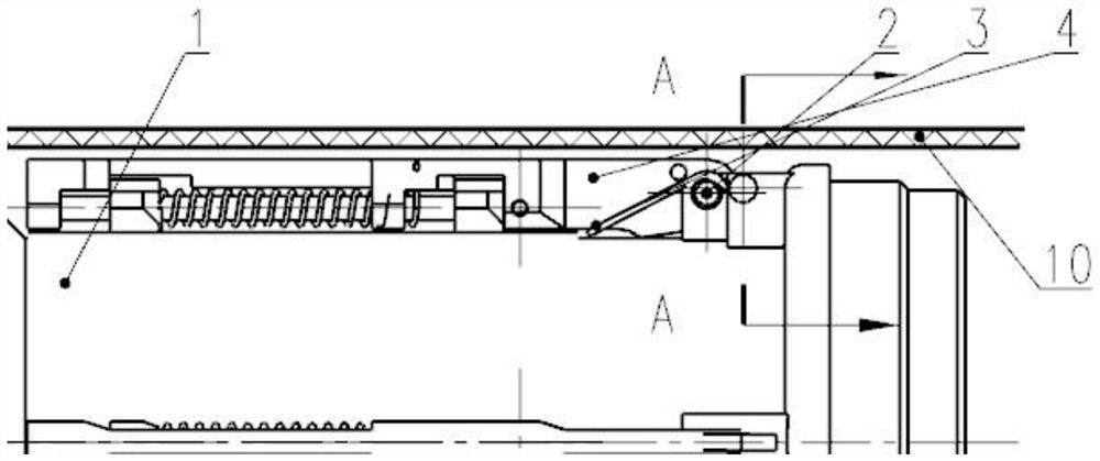
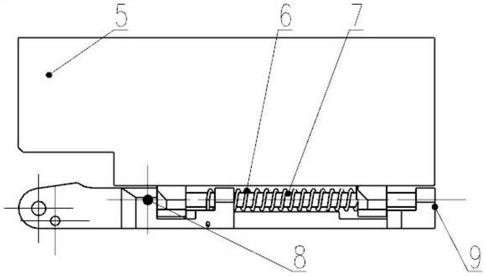
[0030] The small-caliber projectile provided by the preferred embodiment of the present invention-the rapid deployment and reliable locking method of the large-aspect-ratio empennage mechanism, the empennage mechanism is arranged in the lug groove at the middle and rear part of the nozzle, and the torsion spring and the wing torsion spring generate The spring force acts on the middle position of the empennage in the span direction, and the deployment moment is increased by adjusting the torsion spring, the stiffness of the wing torsion spring, and the position and height of the wing shaft.

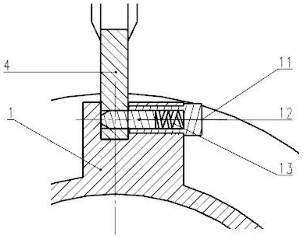
[0031] The locking mechanism is divided into two parts: longitudinal locking and transverse locking; the longitudinal locking mechanism is built inside the nozzle, and the conical pin locking method is used to position and self-lock the longitudina...


PUM


Abstract

The invention belongs to the technical field of projectile body structure design, and relates to a rapid unfolding and reliable locking method for a space folding empennage, which comprises an unfolding mechanism and a locking mechanism which are arranged in a spray pipe and the empennage. The unfolding mechanism acts on the moment of the empennage mechanism by using the spring force of a torsional spring, provides longitudinal unfolding moment for the empennage mechanism, and realizes transverse unfolding of the empennage pieces by using wing torsional springs on the empennage pieces; the locking mechanism is used for positioning and self-locking the longitudinal direction of the empennage mechanism in a taper pin locking manner; and positioning and self-locking are carried out on the tail wing sheet in the transverse direction by adopting a positioning clamping groove in the wing sheet shaft. The problems of rapid unfolding and reliable locking of a small-caliber projectile body and a high-aspect-ratio empennage are solved, the structure is simple, the weight is light, the connecting rigidity of the empennage and the projectile body is good, the flying stability and the flying quality are improved, and the large application and popularization space is achieved.

Description

technical field [0001] The invention belongs to the technical field of structural design of missile empennage, and mainly relates to a rapid deployment and reliable locking method of a large aspect ratio empennage. Background technique [0002] In order to meet the requirements of structural space, a large number of projectiles adopt folding tail fins. Its working principle is: in the state of storage and transportation, the empennage is in a superimposed state and adapts to the inner wall of the launching tube, and the inner wall of the launching tube is used as a constraint. Reliable locking under the action of the tightening mechanism. [0003] Usually, the unfolding mechanism of the foldable empennage generally adopts the following methods: (1) the spring moment generated by the torsion spring is used as the unfolding moment; (2) the compression spring directly acts on the empennage through the spring force to generate the unfolding moment; (3) using the gas pressure ,...

Claims


Application Information

Patent Timeline
IPC IPC(8): F42B10/14
CPCF42B10/14
Inventor 张敏张永励邱瑞宏龙元丰吴永忠李智明向玉伟王若冰袁梦笛余磊张宝秀
Owner 西安现代控制技术研究所
Why Eureka
Try Eureka