Medium-speed multistage centrifugal fan

A centrifugal fan, medium-speed technology, applied in the direction of mechanical equipment, machines/engines, liquid fuel engines, etc., can solve the problems of low speed and low efficiency of multi-stage centrifugal fans, and achieve good aerodynamic performance, low noise and stable performance Effect

Inactive Publication Date: 2019-12-03
HUNAN GUOYAO TECH DEV GRP
View PDF7 Cites 0 Cited by
  • Summary
  • Abstract
  • Description
  • Claims
  • Application Information

AI Technical Summary

Problems solved by technology

[0004] In order to solve the problems of low speed and low efficiency of existing multistage centrifugal fans, a medium-speed multistage centrifugal fan is proposed, which can effectively improve the speed and efficiency of multistage centrifugal fans

Method used


Image

  • Medium-speed multistage centrifugal fan
  • Medium-speed multistage centrifugal fan
  • Medium-speed multistage centrifugal fan

Examples


Embodiment Construction

[0026] In order to make the object, technical solution and effect of the present invention more clear and definite, the present invention will be further described in detail below with reference to the accompanying drawings and examples. It should be understood that the specific embodiments described here are only used to explain the present invention, not to limit the present invention.

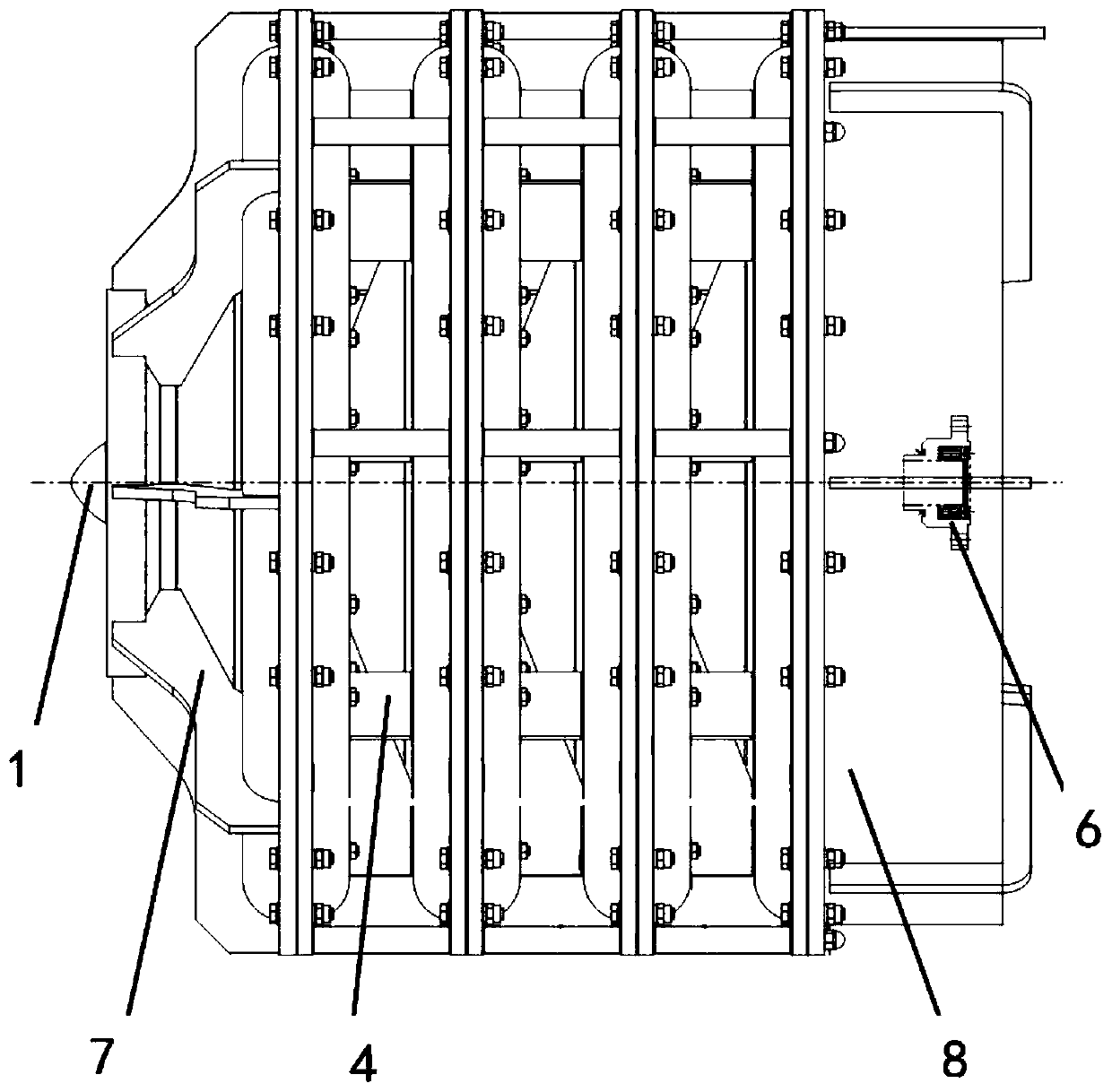
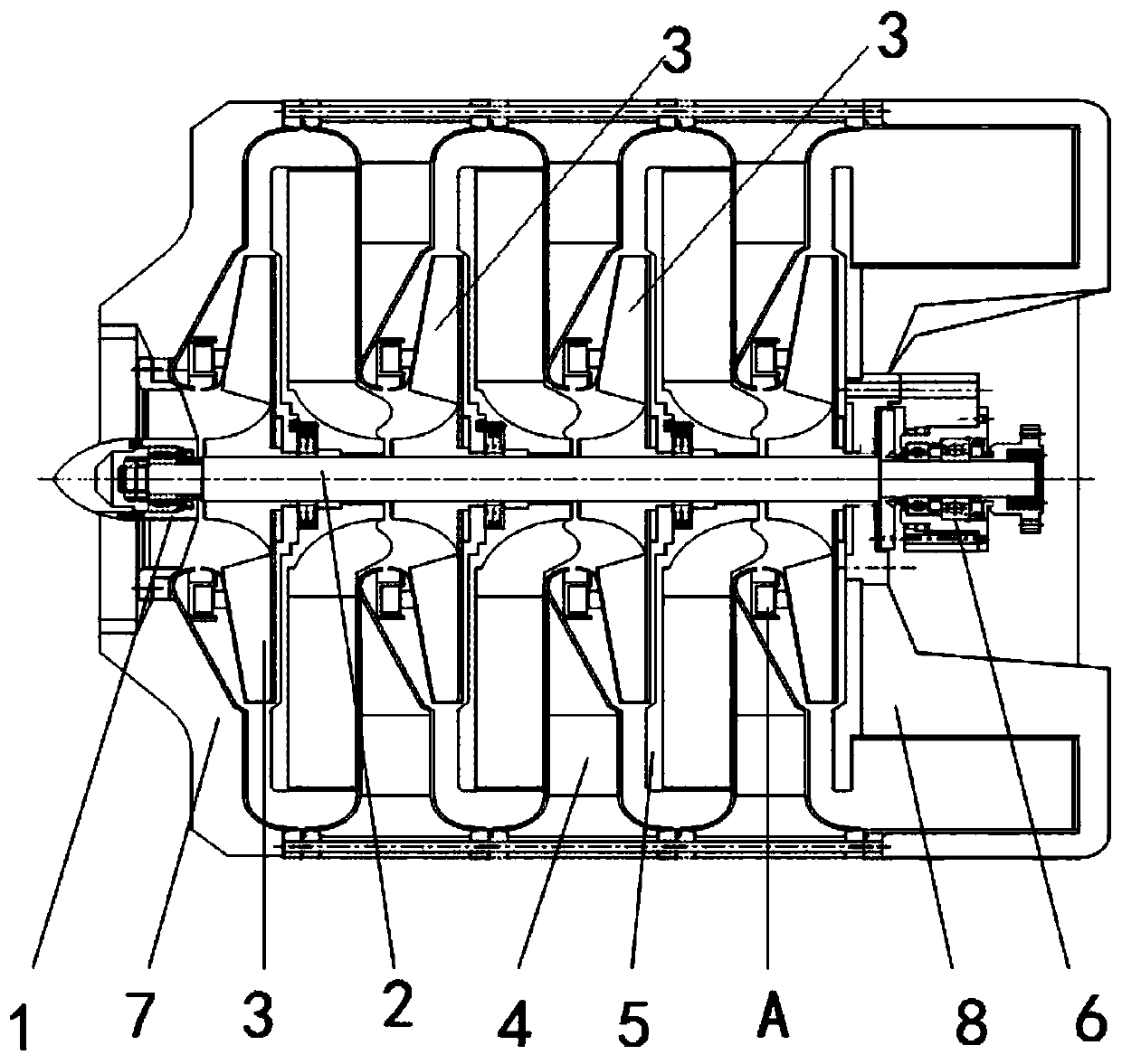
[0027] refer to figure 1 and figure 2 , the present embodiment provides a medium-speed multi-stage centrifugal fan, including a front bearing 1, a main shaft 2, a multi-stage impeller 3, a multi-stage intermediate casing 4, a multi-stage air deflector 5 and a rear bearing 6;

[0028] The front bearing 1 and the rear bearing 6 are respectively installed at both ends of the main shaft 2. The multi-stage impellers 3 are installed and distributed along the axial direction of the main shaft 2. The multi-stage intermediate casing 4 is respectively installed with the multi-stage impellers 3. The ...


PUM


Abstract

The invention provides a medium-speed multi-stage centrifugal fan, comprising a front bearing part, a main shaft, a multi-stage impeller, a multi-stage middle machine shell, a multi-stage air guide disc and a rear bearing part. The front bearing part and the rear bearing part are installed at the two ends of the main shaft respectively, the multi-stage impeller is installed and distributed in theaxial direction of the main shaft; the multi-stage middle machine shell is installed in cooperation with the multi-stage impeller respectively; the multi-stage air guide disc is installed in cooperation with the multi-stage impeller respectively. The impeller in each stage is used for pressurizing air during rotation, and the pressurized air is transmitted to the next stage of impeller through theair guide disc. The main shaft is a metal linear shaft with the length-diameter ratio larger than or equal to 12 and smaller than 25. The fan can reliably operate at the rotating speed of 3000-10000rpm, and the energy efficiency is close to that of a high-speed single-stage centrifugal fan and is far higher than that of a traditional low-speed centrifugal fan.

Description

technical field [0001] The invention relates to the technical field of aerodynamics, in particular to a medium-speed multistage centrifugal fan. Background technique [0002] The multi-stage centrifugal fan is a high-pressure centrifugal fan product. Multiple impellers are installed on the same main shaft. After the air enters the first-stage impeller through the air inlet of the fan, the rotating impeller makes the sucked air obtain kinetic energy, and the diffuser chamber will The kinetic energy of the air is converted into static pressure energy to form compressed air, and then the compressed air enters the air inlet of the second-stage impeller through the air deflector, which increases the air pressure again, and thus circulates into the third, fourth, ... Nth stages The impeller is finally discharged through the air outlet of the fan outlet volute. In fan application conditions, if the pressure acts on the fan inlet, it is negative pressure, and if the pressure acts o...

Claims


Application Information

Patent Timeline
IPC IPC(8): F04D17/12F04D29/053F04D29/08F04D29/42F04D29/58
CPCF04D17/122F04D29/053F04D29/083F04D29/4226F04D29/582
Inventor 文向
Owner HUNAN GUOYAO TECH DEV GRP
Why Eureka
Try Eureka