Dynamic flower-shaped firework setting-off appliance
A dynamic and pyrotechnic technology, which is applied in pyrotechnics, weapon types, offensive equipment, etc., can solve the problems of limiting the effect of fireworks, lack of dynamics, and many safety hazards, and achieve reusable work, convenient installation and use, and improved safety. Effect
- Summary
- Abstract
- Description
- Claims
- Application Information
AI Technical Summary
Problems solved by technology
Method used
Image
Examples
Embodiment 1
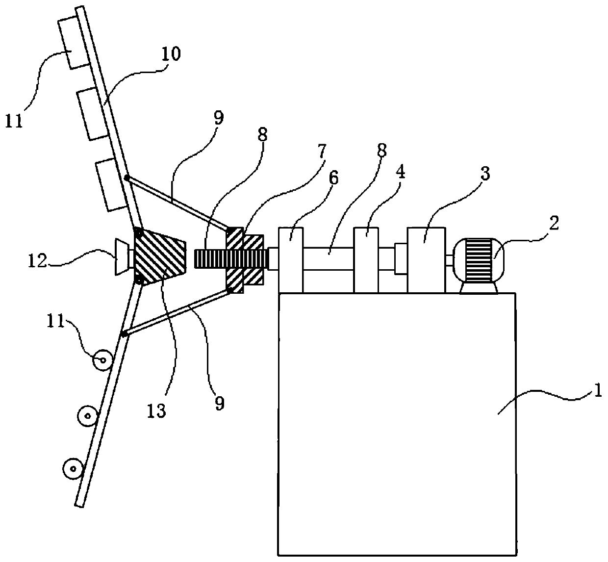
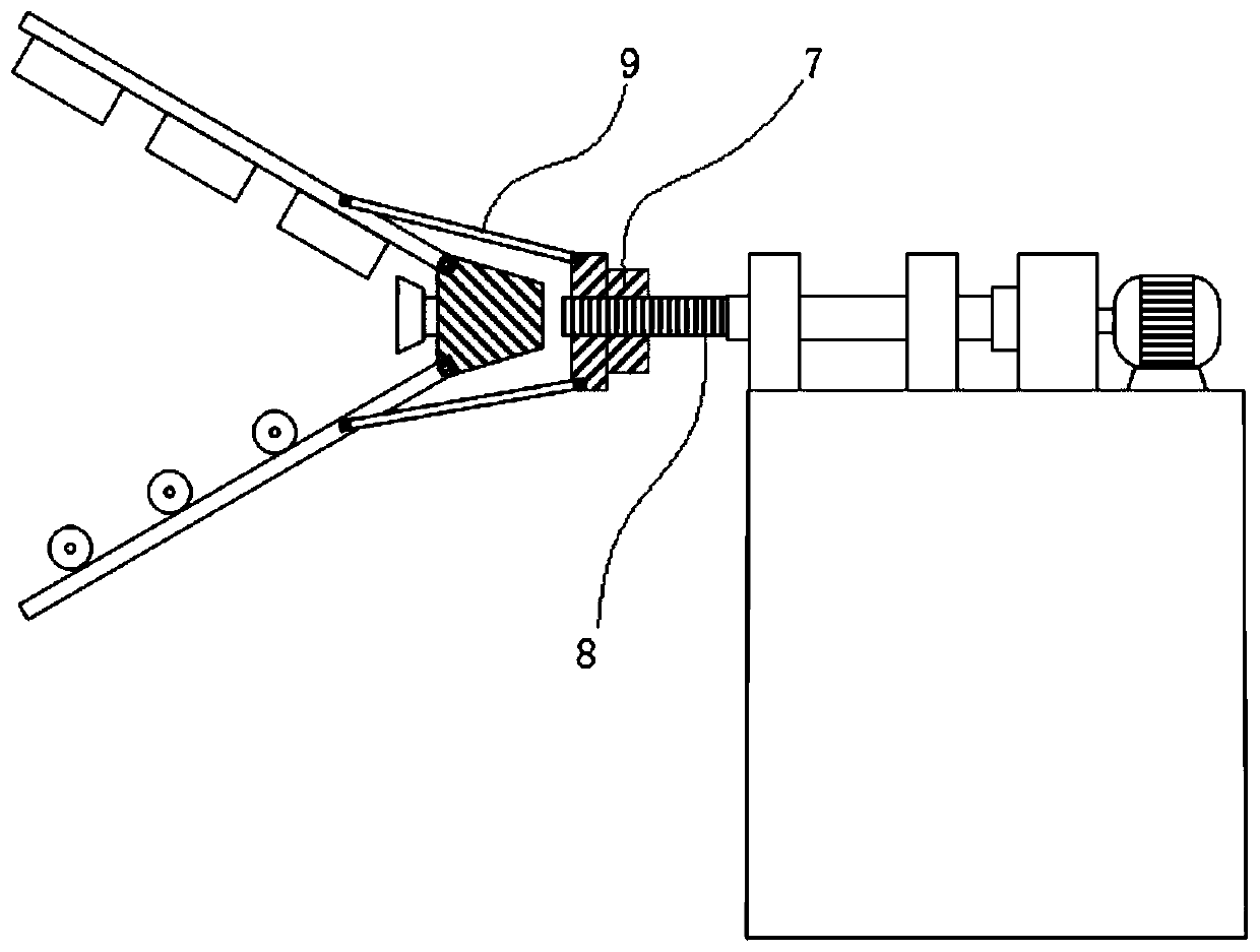
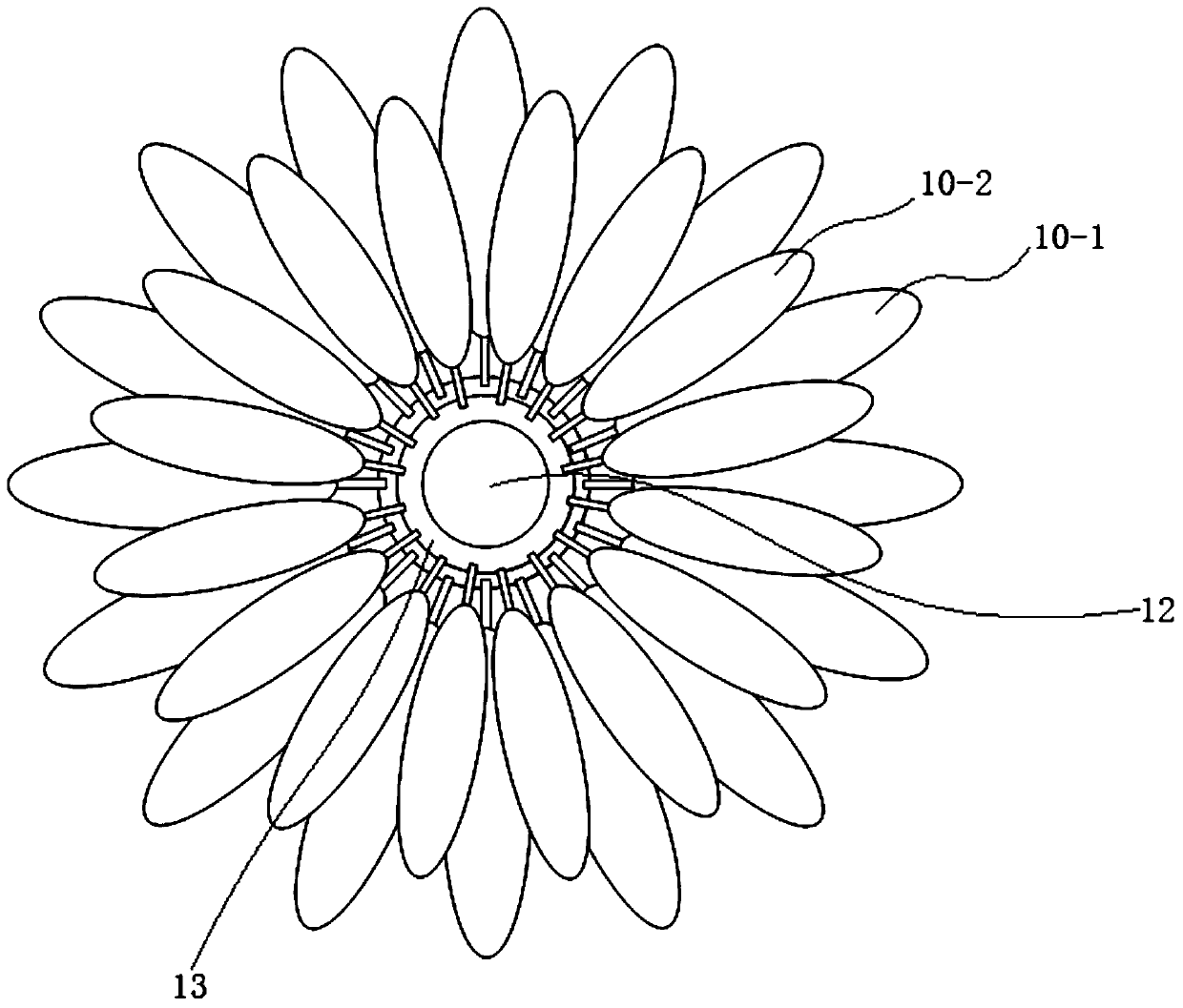
[0023] Embodiment 1: see attached Figure 1-3 , reflecting a specific structure of the present invention, the flower-blooming dynamic firework display device includes a number of petal body parts 10 for installing fireworks 11, and the fireworks 11 can be installed on the petal body parts 10 in various postures or ways, as shown in the figure As shown, the installation postures of the fireworks 11 on the upper petal body part 10 and the lower petal body part 10 are different. It also includes a screw member 8 connected to the rotary drive mechanism. The screw member 8 is installed on the platform 1 through the bearing 6 and the bearing 4. The rotary drive mechanism formed by the reversible motor 2 and the gearbox 3 is connected to the rear end of the screw member 8.
[0024] A front base body 13 and a rear base body 7 are arranged along the axial direction of the screw member 8, the root of each petal body part 10 is hinged on the front base body 13, and the middle part of eac...
Embodiment 2
[0028] Example 2: see Figure 4 , 5 , the difference from Embodiment 1 is that the front base body 204 is fixed on the screw member 201 through the bearing 205 , or the rear base body 202 moves and drives the petal body part 206 through the connecting rod part 203 . The molding of the front base body 204, the petal body part 206 and the installation method of the fireworks 207 are changed.
Embodiment 3
[0029] Embodiment 3: see Figure 6 , 7 , the difference from Embodiment 1 is that the rear base 304 is fixed, the front base 302 is sleeved on the screw member 305 and is provided with an internal thread engaged with the external thread of the screw member 305, and the screw member 305 drives the front base 302 along the screw member. The axial direction of 305 is linearly moved back and forth to shorten the axial distance between the front base 302 and the rear base 304 . Such as Figure 6 , the front base 302 moves to the left, and when the distance expands, the rear base 304 drags the petal body 301 through the connecting rod 303 to open to form the blooming effect of flowers; Figure 7 , the front base 302 moves to the right, and when the distance is reduced, the rear base 304 withstands the petal body 301 through the connecting rod 303 and closes to form a flower closing effect.
PUM
 Abstract
Description
Claims
Application Information
 - R&D
- Intellectual Property
- Life Sciences
- Materials
- Tech Scout
- Unparalleled Data Quality
- Higher Quality Content
- 60% Fewer Hallucinations
Browse by: Latest US Patents, China's latest patents, Technical Efficacy Thesaurus, Application Domain, Technology Topic, Popular Technical Reports.
© 2025 PatSnap. All rights reserved.Legal|Privacy policy|Modern Slavery Act Transparency Statement|Sitemap|About US| Contact US: help@patsnap.com


