A Measuring Method of Groove Angle of Transmission Plane Blazed Grating

A technology of blazed gratings and measurement methods, applied in the field of optics, can solve problems such as high error, complex principles, and many deduction steps, and achieve the effect of low experimental requirements, simple principles, and few deduction steps

Active Publication Date: 2020-11-24
UNIV OF SHANGHAI FOR SCI & TECH
View PDF6 Cites 0 Cited by
  • Summary
  • Abstract
  • Description
  • Claims
  • Application Information

AI Technical Summary

Problems solved by technology

The principle of this method is complicated, there are many deduction steps, and the error is as high as 5%.

Method used


Image

  • A Measuring Method of Groove Angle of Transmission Plane Blazed Grating
  • A Measuring Method of Groove Angle of Transmission Plane Blazed Grating
  • A Measuring Method of Groove Angle of Transmission Plane Blazed Grating

Examples


Embodiment Construction

[0042] The following will clearly and completely describe the technical solutions in the embodiments of the application with reference to the drawings in the embodiments of the application. Apparently, the described embodiments are only some of the embodiments of the application, not all of them. Based on the embodiments in this application, all other embodiments obtained by persons of ordinary skill in the art without making creative efforts belong to the scope of protection of this application.

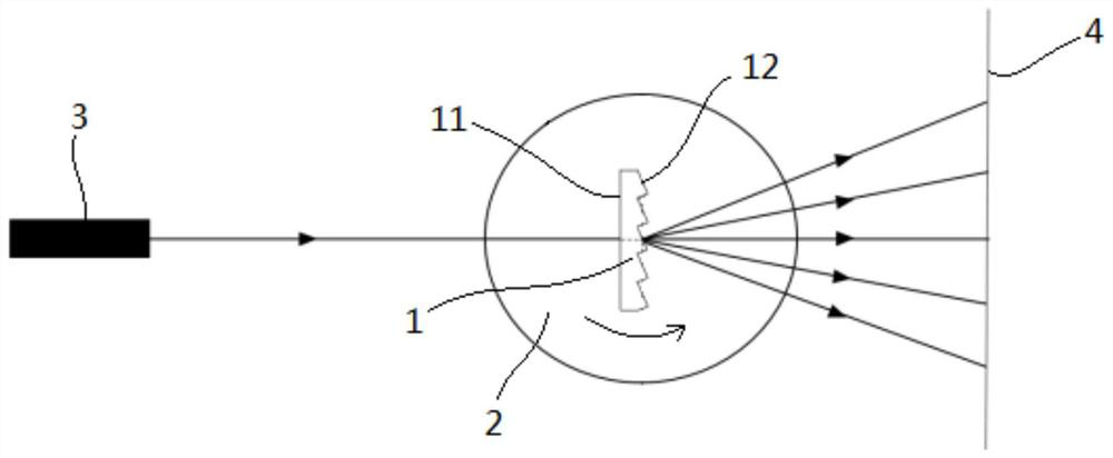
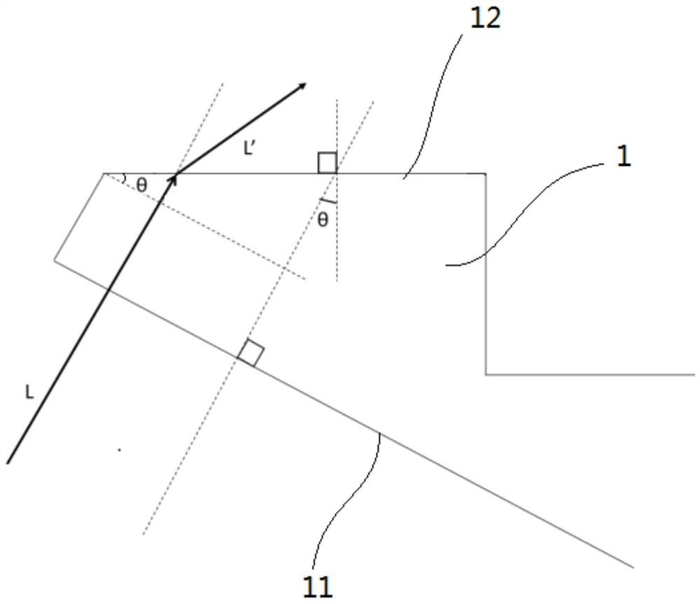
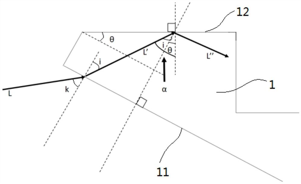
[0043] Such as figure 1 , figure 2 and image 3 As shown in , a method for measuring the groove angle of a transmissive planar blazed grating, before the test starts, a test light path is first built, and the test light path is specifically as follows figure 1 As shown, the blazed grating 1 to be tested is vertically arranged on a precision rotary table 2, and the central axis of the blazed grating 1 is set to coincide with the rotation axis of the precision rotary table 2, that is...


PUM

PropertyMeasurementUnit
wavelengthaaaaaaaaaa
refractive indexaaaaaaaaaa

Abstract

The application discloses a method for measuring a trough angle of a transmissive planar blazed grating. The method comprises the following steps of causing a parallel beam emitted by a line source tobe incident on the blazed grating along a normal direction of the grating surface, and recording an initial angle K1 between a reference line and a zero position of the blazed grating at this time and a light energy value of the line source; keeping the light source stationary, rotating the blazed grating along a central axis of the blazed grating, and continuously detecting the diffracted lightenergy value exiting from the notched facet of the blazed grating; when the absolute value of the difference between two T values of the blazed grating every time rotating for 1 degree is greater thanor equal to 5%, recording the ending angle K2, and calculating the trough angle theta of the blazed grating according to the following formula, wherein n is the refractive index of the blazed gratingsubstrate material, and k=K2-K1. The method for measuring the trough angle described in the application has a simple measurement optical path, low experimental requirements and no need for slicing, and is non-destructive for the blazed grating to be measured.

Description

technical field [0001] The present application relates to the field of optics, in particular to a method for measuring the groove angle of a transmission-type planar blazed grating. Background technique [0002] When the grating is carved into a zigzag groove section, the light energy of the grating is concentrated in a predetermined direction, that is, a certain spectral level. When detecting from this direction, the intensity of the spectrum is the largest, this phenomenon is called blaze (blaze), and this kind of grating is called blazed grating. According to the working principle, it can be divided into transmission blazed grating and reflective blazed grating. [0003] One side of the transmissive flat blazed grating is the grating surface, and the other side is zigzag. There are multiple notched facets on the zigzag side. There is an angle θ between the notched facets and the grating surface, which is called groove shape. horn. The processing error of the groove ang...

Claims


Application Information

Patent Timeline
Patent Type & Authority Patents(China)
IPC IPC(8): G01B11/26
CPCG01B11/26
Inventor 倪争技沈宇航黄元申张翔盛斌张大伟郭谟强
Owner UNIV OF SHANGHAI FOR SCI & TECH
Why Eureka
Try Eureka