Time display method and moon phase display method

A time display and display method technology, which is applied to the mechanical device of time indication, indicates the direction of time and instruments by visual means, can solve the problems such as the lack of decorative environment, lack of display method, practicality and artistry, etc. The effect of enhancing awareness and facilitating the popularization of knowledge

Inactive Publication Date: 2019-07-05
上海墨睿工业设计有限公司
View PDF10 Cites 1 Cited by
  • Summary
  • Abstract
  • Description
  • Claims
  • Application Information

AI Technical Summary

Problems solved by technology

[0003] At present, mechanical or electronic clocks are used to time and calculate the number of days in a month. There is a lack of a new display method, which cannot meet people's con

Method used


Image

  • Time display method and moon phase display method
  • Time display method and moon phase display method
  • Time display method and moon phase display method

Examples


Embodiment 1

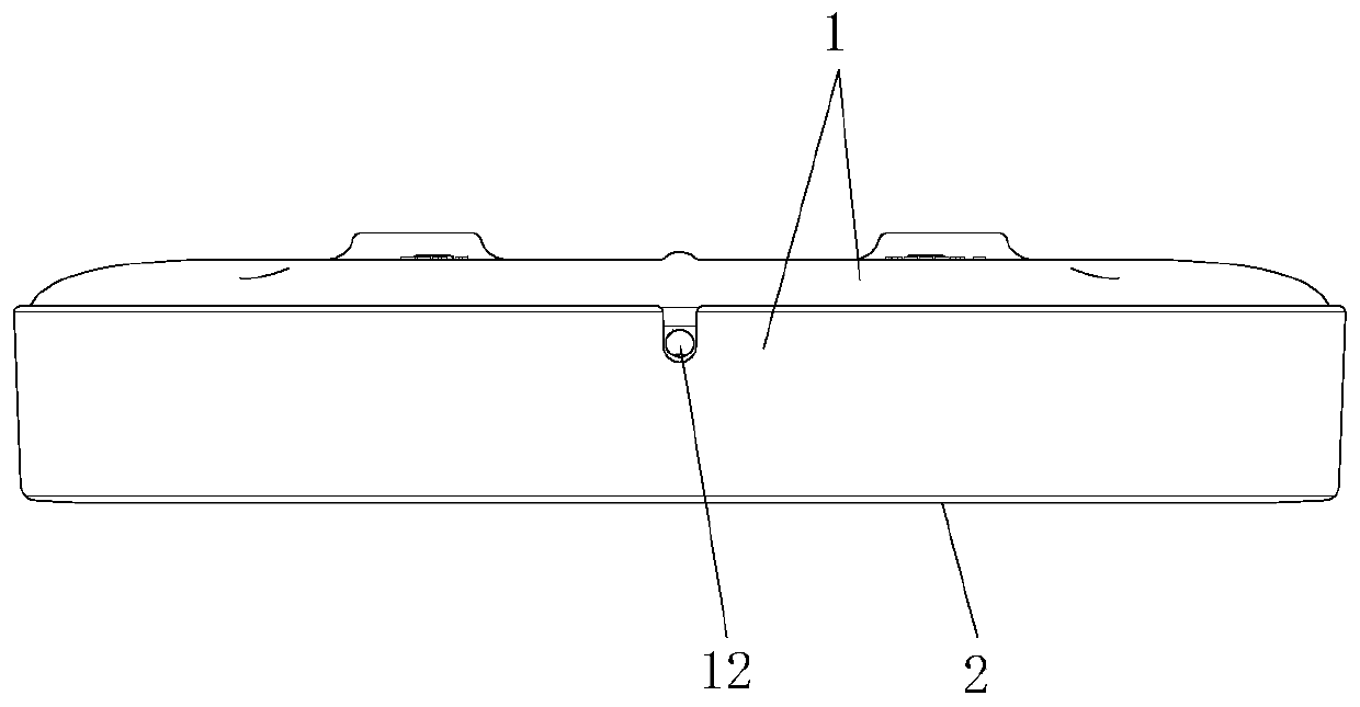
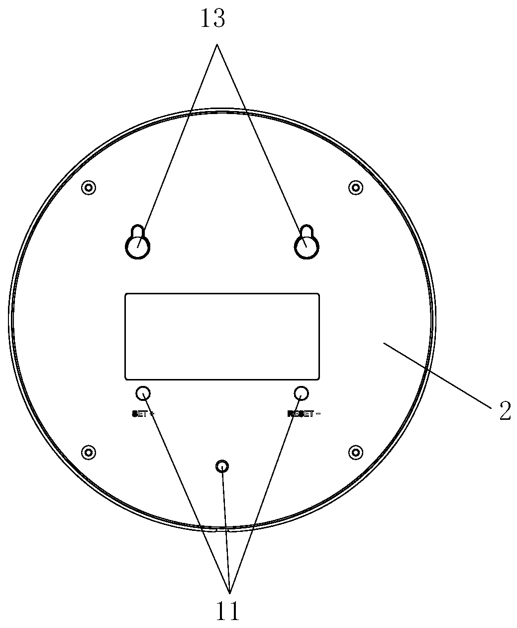
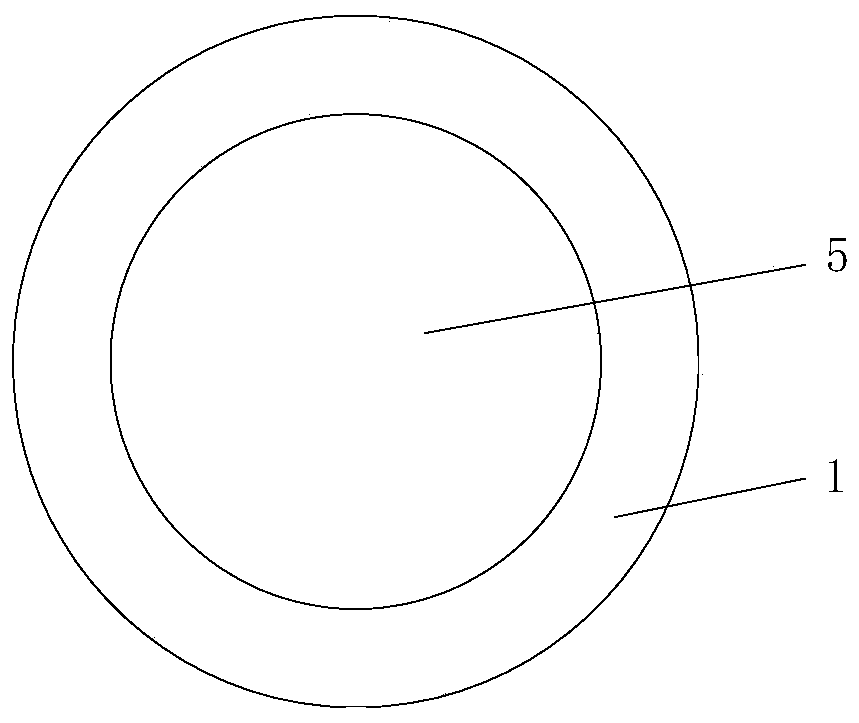
[0038] Such as Figure 1-6 As shown, this embodiment provides a lighting device for simulating a planet, which includes a housing, a luminous element, and a decorative plate 3 for simulating the surface of a planet. Wherein the decorative plate 3 is in the shape of a disc, and its outer surface is provided with a concave-convex texture simulating a planet. When the light is irradiated from the side of the ornamental plate 3, since the concave-convex texture will block part of the light, the edge portion of the ornamental plate 3 will be brighter than the middle portion, further improving the realism of the simulated planet. The following materials and methods can be used for the production of decorative plate 3:

[0039] It can be shaped by ceramic engraving over-molding, which replaces the ceramic material with a mixture of resin and cement. Metal and resin mixed materials can also be used, and the process of die-casting, pouring and CNC milling can be used to form, and the...

Embodiment 2

[0046] Such as Figure 7-10 As shown, most of the technical features in the second embodiment are the same as those in the first embodiment, except that:

[0047]The luminous part includes a circular circuit board 6, and the upper surface of the circuit board 6 is distributed with LED lamp groups 8 along the circumferential direction; the circuit board 6 is fixed on the mounting column 4, and the decorative plate 3 is fixed on The upper surface of the circuit board 6 and the LED lamp group 8 surround the surroundings of the decorative plate 3 . The decorative plate 3 is fixed on the upper surface of the circuit board 6 through the second light guide ring 14; the cross section of the second light guide ring 14 is L-shaped, and the end surface of one of the two ends of the second light guide ring 14 is provided with a ring through the groove 10 so that the end surface of this end covers the LED lamp group 8, and the other end is sandwiched between the upper casing 1 and the dec...

Embodiment 3

[0050] This embodiment provides a time display method, which is applied to the lighting devices for simulating planets in Embodiments 1 and 2, wherein twelve groups of LED lamps are provided, and each lamp group is provided with five LEDs lamp. The five LED lamps are evenly distributed in the interval from the last full hour to the full hour of the luminous element. Each lamp represents 12 minutes, there are 60 lamps in total, 60 lamps represent 12 hours, and every time a lamp is lit, it means that 12 minutes have elapsed. The lights are all on and all off in sequence to indicate the time of day.

[0051] This method comprises the following steps:

[0052] Step 1: From 12 o'clock to 24 o'clock, the circuit board gradually lights up the light group at the direction of 13-24 o'clock on the luminous part, and the light group corresponding to each hour is in the state of maximum brightness and maintains the luminous state;

[0053] From 24:00 to 12:00, the circuit board gradual...


PUM


Abstract

The invention discloses a time display method and a moon phase display method. The time display method comprises the following steps that step 1, from 12 o'clock to 24 o'clock, the circuit board gradually lights up the light sets on the light-emitting part in the directions of 13-24 o'clock, wherein the lamp sets corresponding to each integral point are in the maximum state of brightness; step 2,from 24 o'clock to 12 o'clock, the circuit board gradually extinguishes the light sets on the light-emitting part in the directions of 1-12 o'clock, wherein the lamp sets corresponding to each integral point are in the extinguishing state; and step 3, the steps 1 and 2 are repeated one time every day. The moon phase display method comprises the following steps that step 1, in the first half of anymonth of the lunar calendar, the circuit board gradually lights up the light sets at 11 o'clock to 5 o'clock on the light-emitting part in both clockwise and counterclockwise directions; and step 2,in the second half of the month, the circuit board gradually extinguishes the light sets at 5 o'clock to 11 o'clock on the light-emitting part in both clockwise and counterclockwise directions. The time display method and moon phase display method break the conventional time display method and increase the understanding of the moon phase change.

Description

technical field [0001] The invention relates to the technical field of timing, in particular to a time display method and a moon phase display method. Background technique [0002] Present clocks display the time by pointing the hands at the time points on the dial. This time display method is very conventional and easy to understand. Some clocks are inlaid with calendar display parts, and the year, month and day can also be seen at the same time. [0003] At present, mechanical or electronic clocks are used to time and calculate the number of days in a month. There is a lack of a new display method, which cannot meet people's continuously improving requirements for quality of life. Conventional clocks do not combine practicality and artistry, and cannot play the role of decorating the environment and rendering the atmosphere. In addition, the way the clock displays the time gradually makes people forget the ancient way of judging the time by the changes of the moon phases...

Claims


Application Information

Patent Timeline
IPC IPC(8): G04B19/10G04B19/26
CPCG04B19/106G04B19/268
Inventor 庞鸣
Owner 上海墨睿工业设计有限公司
Why Eureka
Try Eureka