Eureka AIR delivers breakthrough ideas for toughest innovation challenges, trusted by R&D personnel around the world.

Metal window assembly with bonding structure for bonding to window frame

A combination of structure and metal technology, applied in the direction of building components, door/window accessories, building construction, etc., can solve the problem that the outer edges of the window frame are not precisely aligned with each other, the shape of the internal structure of the window frame is complicated, and the use of Dissatisfaction with the appearance of the user and other problems, to achieve the effect of easy assembly and operation, easy operation, and prevention of interference

Active Publication Date: 2021-03-09
GEONWON
View PDF9 Cites 0 Cited by
  • Summary
  • Abstract
  • Description
  • Claims
  • Application Information

AI Technical Summary

Problems solved by technology

[0006] However, since the coupling structure in the prior art is configured to avoid installation interference and operation interference with various additional installation members (such as sealing members, etc.) arranged at the end portions of the above-mentioned respective window frames, There is a problem that the shape of the internal structure of each window frame is inevitably complicated
[0007] In addition, since the bonding structure in the prior art is configured to be bonded to the center side portion of the inner side of each window frame, there is a problem that the above-mentioned outer edge side portions of the respective window frames are not precisely aligned with each other, and some floating occurs. Phenomena or overlapping phenomena resulting in unsightly appearance
Of course, in some prior art, there is also provided a structure that is closely fixed on the outer surface of each window frame, but in this case, it causes users to be dissatisfied with the appearance.

Method used


Image

  • Metal window assembly with bonding structure for bonding to window frame
  • Metal window assembly with bonding structure for bonding to window frame
  • Metal window assembly with bonding structure for bonding to window frame

Examples


Embodiment Construction

[0055] Below, refer to Figure 1 to Figure 36 Preferred embodiments of the metal window unit of the present invention will be described.

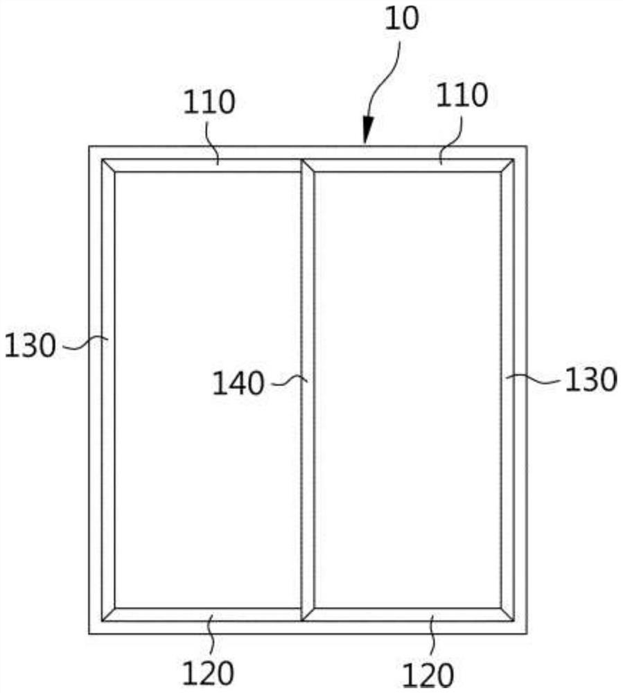
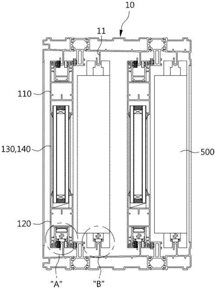
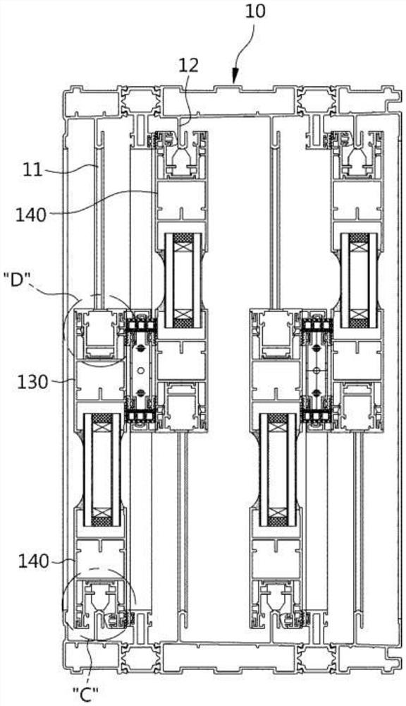
[0056] figure 1 is a state diagram schematically shown for explaining a state in which a metal window assembly is installed in a window frame according to an embodiment of the present invention, figure 2 It is a longitudinal sectional view for explaining a state in which a metal window assembly according to an embodiment of the present invention is installed in a window frame, image 3 It is a cross-sectional view for explaining a state in which a metal window assembly according to an embodiment of the present invention is installed in a window frame.

[0057] Thus, the metal window assembly according to the embodiment of the present invention is configured in a structure that opens or closes while sliding left and right in the window frame 10, and as an example, two window assemblies on the indoor side and two window assemblies on the ...


PUM


Abstract

The present invention provides a metal window assembly, comprising: two horizontal side window frames and two vertical side window frames, two opening side joint structures and two closing side joint structures, and the above joint structures not only strengthen The bonding strength between the various window frames can also perform the functions of airtightness, shock absorption, and movement and shaking prevention. Various additional setting components are set in it, so as to eliminate the problems in the prior art, such as when assembling each combination structure, the phenomenon of interference with assembly or the difficulty of assembly due to the above-mentioned various additional setting components and the provision of unstable combination structures, etc. question.

Description

technical field [0001] The present invention relates to window assemblies, and more particularly to a novel metal window assembly having bonding structures for bonding window frames, which can guide precise bonding between horizontal side window frames and vertical side window frames and Maintaining a stable combined state can especially prevent the expansion or level difference of the joint between the two window frames, while simplifying the structure for combining various additional installation components. Background technique [0002] In general, window units refer to various windows or doors that are installed in openings such as windows or entrances to block the inside and outside of a building, and can be classified into wooden window units and metal window units according to the materials used, or Plastic window components, etc. [0003] Such a window unit is composed of a window (glass) and a window frame bonded to the peripheral surface of the window, and is inst...

Claims


Application Information

Patent Timeline
Patent Type & Authority Patents(China)
IPC IPC(8): E06B3/46E05F7/04E05D15/06
CPCE05D15/0665E05F7/04E05Y2201/222E05Y2201/684E05Y2201/688E05Y2900/148E06B3/4609
Inventor 诸廷元
Owner GEONWON
Why Eureka
Eureka Blog
Learn More