
Lumen stent system

A stent system and lumen technology, applied in the field of interventional medical devices, can solve the problems of inability to adjust the stent release position, difficult to accurately control the lumen stent release position, inability to accurately control the lumen stent, etc.

Pending Publication Date: 2019-07-09
LIFETECH SCIENTIFIC (SHENZHEN) CO LTD
View PDF7 Cites 4 Cited by
  • Summary
  • Abstract
  • Description
  • Claims
  • Application Information

AI Technical Summary

Problems solved by technology

The delivery and release method of this endoluminal stent cannot adjust the release position of the stent after the sheath is withdrawn
For endoluminal stents with shortening characteristics, when they are released from the sheath, they will shorten from the distal end to the proximal end, so it is difficult to precisely control the release position of the endoluminal stent
Since the existing luminal stent delivery device cannot adjust the position of the luminal stent twice after the luminal stent is released, it cannot accurately control the release position of the luminal stent, and it is difficult to meet the clinical application requirements, especially when There are many branch vessels in the diseased blood vessel where the luminal stent is released, and it is more necessary to precisely adjust the release position of the luminal stent

Method used


Image

  • Lumen stent system
  • Lumen stent system
  • Lumen stent system

Examples


Embodiment 1

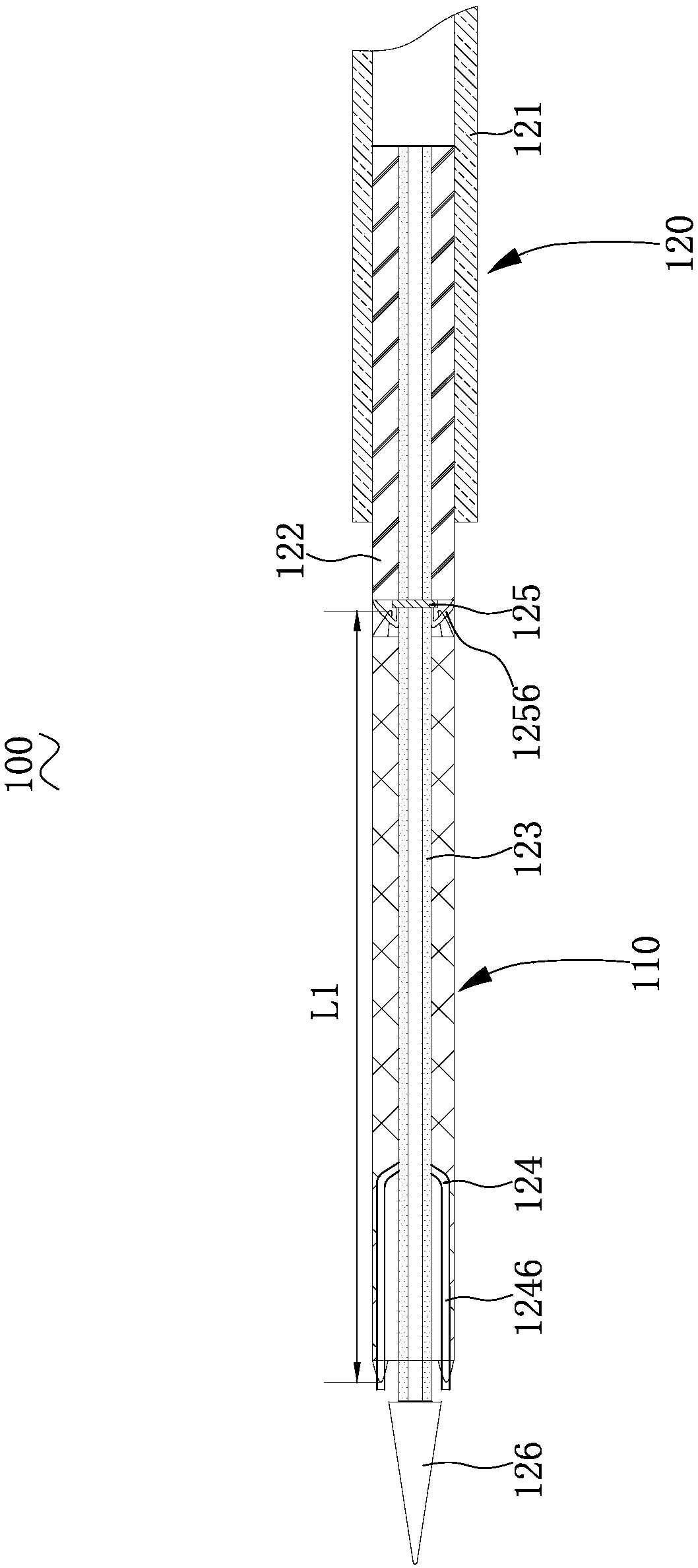
[0031] see figure 1 , a lumen stent system 100 according to an embodiment, comprising a lumen stent 110 and a delivery device 120 for delivering the lumen stent 110 . The endoluminal stent 110 is loaded in the delivery device 120, and then delivered to the diseased part of the human body.

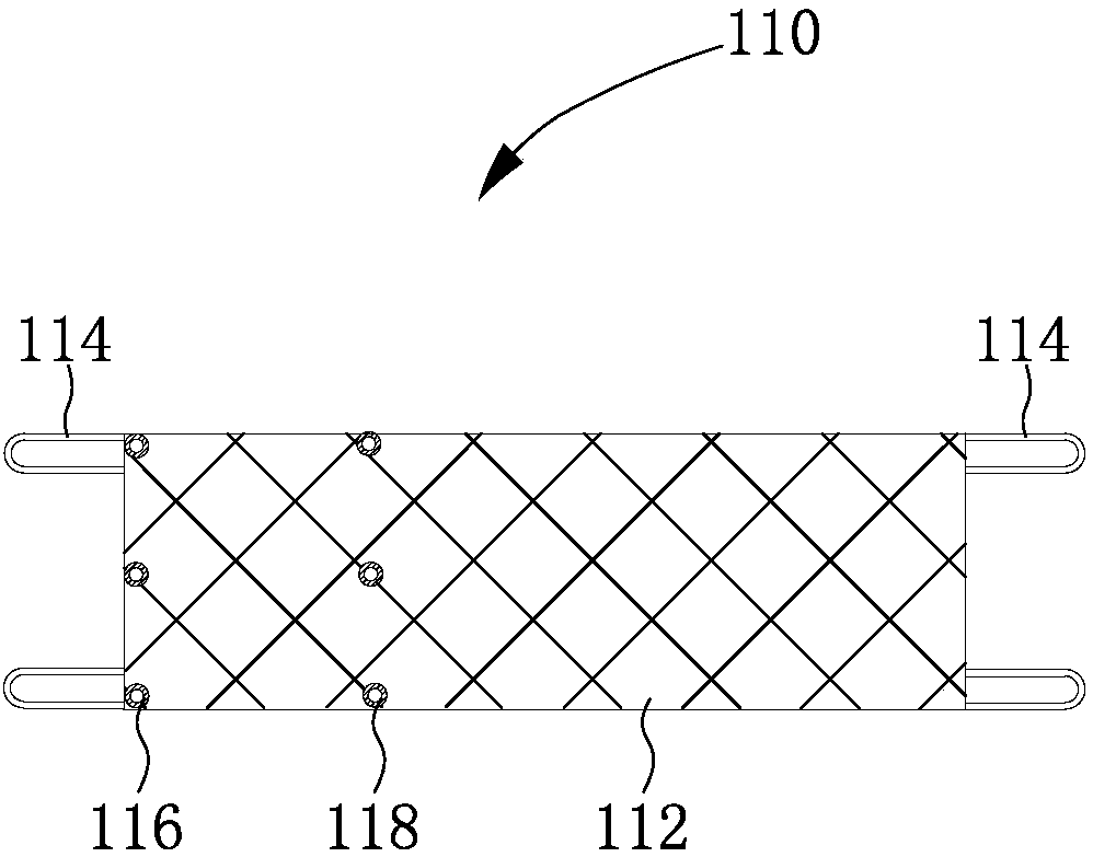
[0032] see figure 2 The endoluminal stent 110 includes a stent body 112 and a plurality of bare coils 114 disposed at the proximal end and the distal end of the stent body 112 . The stent body 112 is a lumen structure. In a natural state (a state without any external force), the outer diameter of the endoluminal stent 110 is R0 (nominal outer diameter), and the length is L0 (nominal length). Wherein, R0 refers to the outer diameter of the stent main body 112 , and L0 refers to the sum of the lengths of the proximal bare wave coil 114 and the distal bare wave coil 114 of the stent main body 110 .

[0033] The number of the proximal bare coils 114 and the distal bare coils 114 are equal,...

Embodiment 2

[0069] see Figure 11 , the luminal stent system of embodiment 2, comprising a luminal stent ( Figure 11 not shown) and a delivery device 220 for delivering the endoluminal stent.

[0070] The structure of the endoluminal stent is the same as that of the endoluminal stent 110 in Embodiment 1, and will not be repeated here.

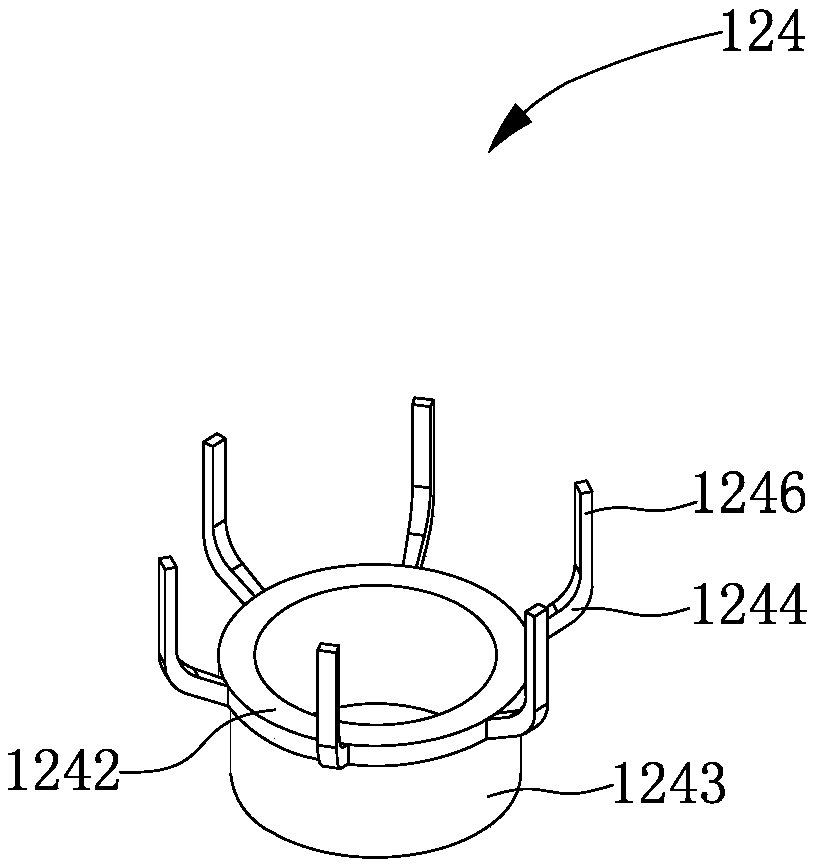
[0071] The delivery device 220 includes a sheath tube 221 , a push tube 222 , an inner core tube 223 , a first anchor 224 , a second anchor 225 and a guide head 226 . The structures of the sheath tube 221 , the pusher tube 222 , the inner core tube 223 , the first anchor 224 and the guide head 226 are the same as those of the delivery device 120 in Embodiment 1, and will not be repeated here. Different from the delivery device 120 , the delivery device 220 further includes an outer core tube 227 , and the structure of the second anchor 225 is different from that of the second anchor 125 .

[0072] The push tube 222 is passed through the sheath tube 221...

Embodiment 3

[0077] see Figure 12 , the lumen stent system 300 of Embodiment 3, comprising a lumen stent 310 and a delivery device 320 for delivering the lumen stent.

[0078] The lumen stent system 300 of the third embodiment is basically the same as the lumen stent system 100 of the first embodiment. Lumen stent system 300 includes a sheath ( Figure 12 not shown), push tube 322, inner core tube 323, first anchor 324, second anchor 325 and guide head 326. The difference between the lumen stent system 300 and the lumen stent system 100 is that the second anchor 325 is different from the second anchor 125 , and the push tube 322 is different from the push tube 122 . Moreover, a locking device 327 is provided at the proximal end of the delivery device 320 . The locking device 327 can be arranged on the handle at the proximal end of the delivery device 320 , and the handle is connected with the inner core tube 323 .

[0079] The second anchor 325 is at least one pull wire, one end of th...


PUM


Abstract

A lumen stent system comprises a lumen stent and a conveying device. The conveying device comprises a sheath, a push tube, an inner core tube, a first anchoring member and a second anchoring member, the push tube is penetratingly arranged in the sheath, the inner core tube penetrates the push tube and extends out from the sheath, the first anchoring member is arranged at the far end of the inner core tube, at least part of the second anchoring member is arranged at the far end of the push tube, and the first anchoring member and the second anchoring member are connected with the far end and the near end of a lumen stent respectively to respectively provide first axial acting force and a second axial acting force opposite in direction so as to load the lumen stent into a cavity formed by surrounding of the inner core tube and the sheath. When the sheath moves to the far end of the sheath along the axial direction of the inner core tube to be flush with the far end of the push tube, thefar end of the lumen stent maintains connection with the first anchoring member while the near end of the same maintains connection with the second anchoring member to enable outer diameter of the lumen stent to be smaller than 90% that of the same in a natural state at least. The lumen stent system can accurately control release position of the lumen stent.

Description

technical field [0001] The invention relates to the field of interventional medical devices, in particular to a lumen stent system. Background technique [0002] At present, in the field of interventional medicine, interventional surgery with compressible lumen stent has become the main method for the treatment of vascular stenosis, aneurysm and dissection due to its small trauma, few complications and good effect. [0003] The lumen stent generally adopts a compressible stent and compresses it into a hollow catheter. Through the puncture port of the human lumen, the stent compressed in the catheter is sent to the lesion under the guidance of digital imaging equipment, and then Through a certain method, the stent is freed from the constraints of the catheter, and the stent is deployed by its own radial support force and attached to the vessel wall to achieve the purpose of treating or alleviating the disease. [0004] In the prior art, the metal structure of the luminal ste...

Claims


Application Information

Patent Timeline
IPC IPC(8): A61F2/966A61F2/86
CPCA61F2/86A61F2/966A61F2002/9505A61F2002/9665
Inventor 肖本好王琴
Owner LIFETECH SCIENTIFIC (SHENZHEN) CO LTD
Learn More