
Rail height adjusting method suitable for rail with baffle parts

An adjustment method and track technology, which is applied to tracks, roads, fixed rails, etc., can solve the problems of fast and accurate track height adjustment on ballastless tracks, fewer backing plates under rails, and waste of resources, etc., to achieve improved Set up efficiency and set up security, improve precision and accuracy, avoid directional effects

Active Publication Date: 2019-07-09
武汉坤能轨道系统技术有限公司
View PDF8 Cites 3 Cited by
  • Summary
  • Abstract
  • Description
  • Claims
  • Application Information

AI Technical Summary

Problems solved by technology

However, in the prior art, the track height adjustment of the rail is often through the overall replacement of the under-rail backing plate, and the replaced under-rail backing plate often cannot be used again and needs to be scrapped directly, resulting in an extreme waste of resources; at the same time, due to The specifications of under-rail backing plates in the prior art are often less, so that the flexibility of track height adjustment is limited, and the accuracy of track height adjustment cannot be fully guaranteed; moreover, when using the existing fastener system for track height adjustment, it is often necessary to The entire fastener system is removed for corresponding adjustments, resulting in low efficiency of track height adjustment and increased rail maintenance costs
Therefore, the existing fastener system has certain application limitations, and cannot fully satisfy the rapid and accurate adjustment of the track height on the ballastless track.

Method used


Image

  • Rail height adjusting method suitable for rail with baffle parts
  • Rail height adjusting method suitable for rail with baffle parts
  • Rail height adjusting method suitable for rail with baffle parts

Examples


Embodiment Construction

[0045] In order to make the object, technical solution and advantages of the present invention clearer, the present invention will be further described in detail below in conjunction with the accompanying drawings and embodiments. It should be understood that the specific embodiments described here are only used to explain the present invention, not to limit the present invention.

[0046] In addition, the technical features involved in the various embodiments of the present invention described below can be combined with each other as long as they do not constitute a conflict with each other.

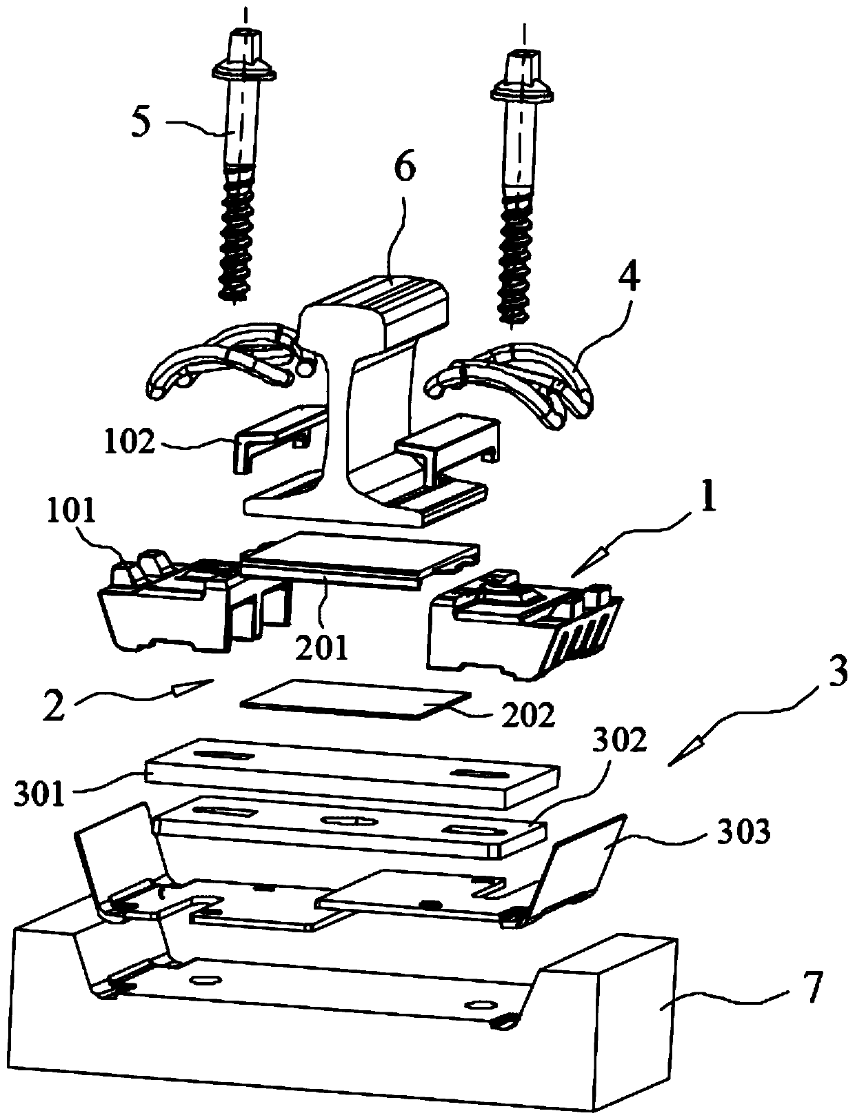
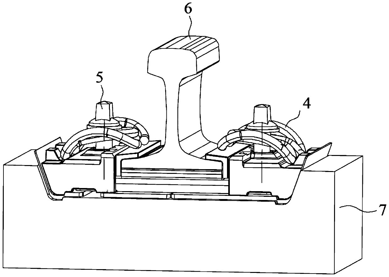
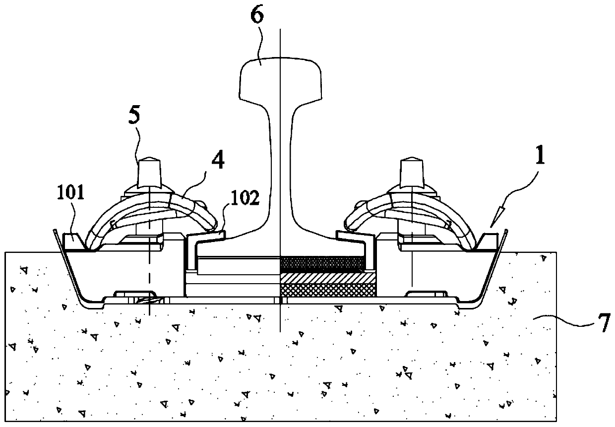
[0047] In the preferred embodiment of the utility model, the structure of the inseparable fastener system applicable to the shoulder sleeper is as follows: Figure 1~4 As shown in , wherein the fastener system includes a gauge adjustment unit 1, a first height adjustment assembly 2, a second height adjustment assembly 3, an elastic bar 4 and a fastening bolt 5, through the above-mention...


PUM


Abstract

The invention discloses a rail height adjusting method suitable for a rail with baffle parts, and belongs to the technical field of rail fasteners. By correspondingly arranging an under-rail cushion plate, an under-rail fine-adjustment cushion plate and first height adjusting cushion plates, preferably setting the sizes of all the cushion plates and selecting corresponding cushion plates in adjustment processes, steel rail height adjustment within the range of -4 mm to 22 mm is effectively achieved. The rail height adjusting method is implemented by adopting a fastener system comprising the under-rail cushion plate, the under-rail fine-adjustment cushion plate and the first height adjusting cushion plates and is simple in step and convenient to operate, the height of a steel rail on a railsleeper with the baffle parts is effectively adjusted, the adjustment process is simple, the reliability is high, the height adjustment range of the steel rail is wide, the flexibility of an adjustment scheme is high, the height adjusting requirements of the steel rail can be fully met, the accuracy and efficiency of steel rail height adjustment are improved, and thus the rail height adjusting method has good application prospects and high application and popularization value.

Description

technical field [0001] The invention belongs to the technical field of track fasteners, and in particular relates to a track height adjustment method suitable for a track with a shoulder stop. Background technique [0002] In the ballastless track, the fastener system is widely used. As the intermediate connecting part of the rail and the sleeper, it plays the role of fixing the rail to the sleeper, and prevents the longitudinal and lateral movement of the rail relative to the sleeper while maintaining the gauge. Move to achieve a stable setting of the rail on the sleeper. [0003] Since most of the existing ballastless tracks use concrete sleepers, the sleeper’s elasticity is poor, so the fastener system is required to provide a certain degree of elasticity while ensuring sufficient strength and durability; at the same time, since the ballastless track may There are certain differences, such as differences in height, lateral offset, etc. Therefore, in order to ensure the a...

Claims


Application Information

Patent Timeline
Patent Type & Authority Applications(China)
IPC IPC(8): E01B9/38E01B9/42E01B9/48E01B9/68
CPCE01B9/38E01B9/42E01B9/483E01B9/68E01B2204/06
Inventor 梅海军许亮
Owner 武汉坤能轨道系统技术有限公司
Learn More