
Electromagnetic switching valve

A technology for electromagnetic switching valves and valve bodies, which is applied to valve details, multi-way valves, valve devices, etc., and can solve problems such as unsatisfactory working conditions

Pending Publication Date: 2019-07-09
ZHEJIANG SANHUA INTELLIGENT CONTROLS CO LTD
View PDF12 Cites 1 Cited by
  • Summary
  • Abstract
  • Description
  • Claims
  • Application Information

AI Technical Summary

Problems solved by technology

[0008] The above electromagnetic four-way valve is suitable for the refrigeration system of household air conditioners, but with the development of technology, the application fields of electromagnetic switching valves continue to expand. For example, in the field of automotive air conditioning, electromagnetic switching valves are also required to switch the direction of refrigerant flow. , especially the carbon dioxide refrigerant commonly used in automobile air conditioners, the use conditions are different from those of ordinary household air conditioners. If the above electromagnetic four-way valve is directly applied to automobile air conditioners, the corresponding working conditions cannot be met

Method used


Image

  • Electromagnetic switching valve
  • Electromagnetic switching valve
  • Electromagnetic switching valve

Examples


Embodiment Construction

[0029] In order to enable those skilled in the art to better understand the technical solutions of the present invention, a further detailed description will be given below with reference to the accompanying drawings and specific embodiments.

[0030] Please refer to figure 2 , image 3 , Figure 4 , figure 2 Is a structural schematic diagram of the electromagnetic switching valve provided in the first embodiment of the present invention in the first working state, image 3 Is a schematic structural diagram of the second working state of the electromagnetic switching valve provided by the first embodiment of the present invention, Figure 4 It is a schematic diagram of the appearance of the electromagnetic switching valve provided by the first embodiment of the present invention.

[0031] The electromagnetic switching valve includes a main valve and a pilot valve. The main valve 1 includes a main valve body 11. The main valve body 11 can be processed by metal such as stainless ste...


PUM


Abstract

The invention discloses an electromagnetic switching valve which is characterized by comprising a main valve and a pilot valve, and the pilot valve comprises a first pilot valve and a second pilot valve; the first pilot valve comprises a first valve body and a first coil which are matched with each other; the second pilot valve comprises a second valve body and a second coil which are matched witheach other; the first valve body comprises a first flow guide part, and the second valve body comprises a second flow guide part; the main valve comprises a main valve body, and the main valve body comprises a main valve cavity; two sides, in the central axis direction of the main valve body, of the main valve body are fixedly connected with the first pilot valve and the second pilot valve correspondingly; the first flow guide part and the main valve body are fixed in a press fit and welding mode, and the second flow guide part and the main valve body are fixed in a press fit and welding mode. According to the electromagnetic switching valve provided by the invention, the welding operation of connecting pipes is reduced, and the potential risks that too many welding parts are prone to failure due to high pressure and vibration can be reduced.

Description

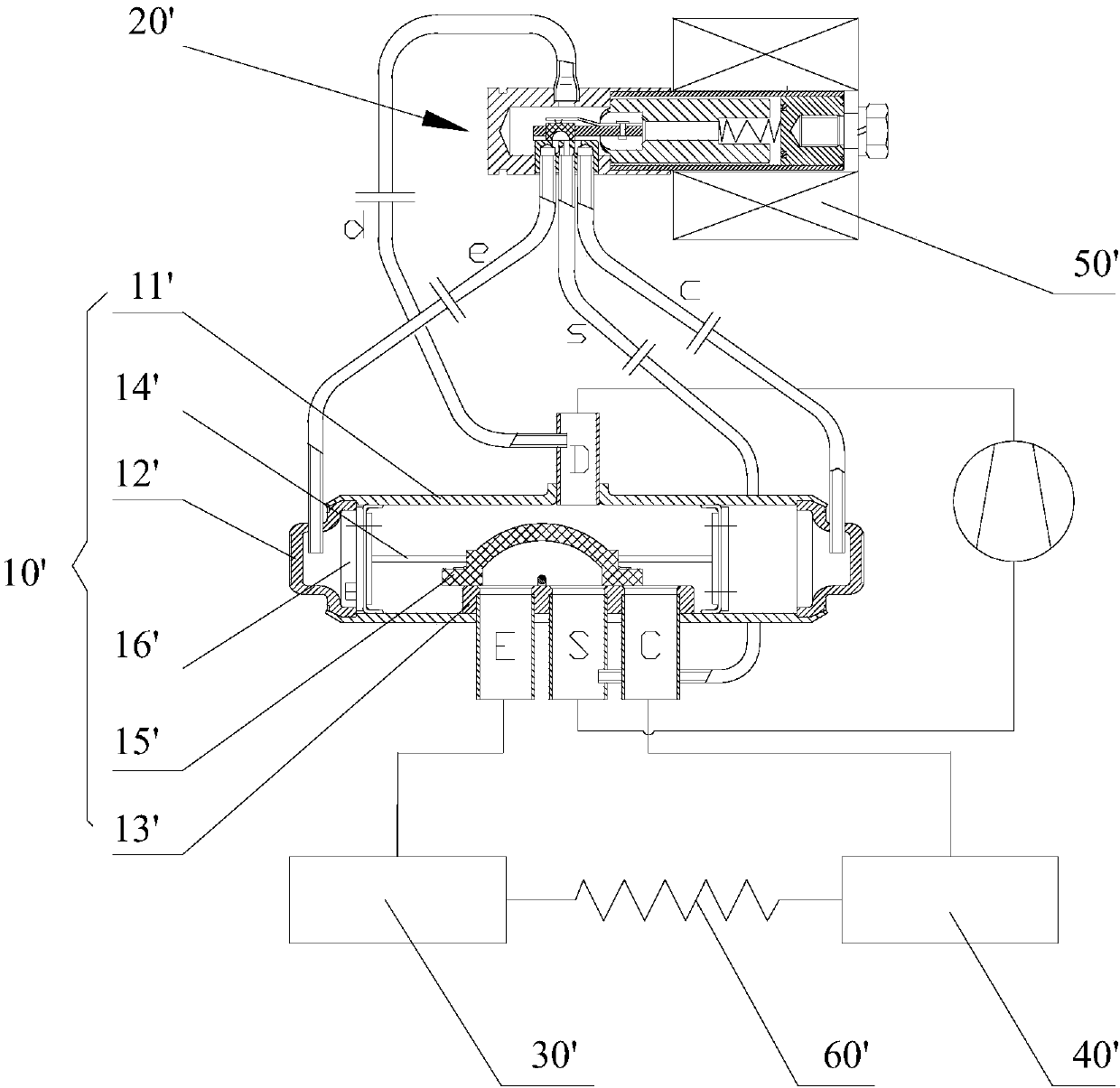
Technical field [0001] The invention relates to the field of refrigeration control, and in particular to an electromagnetic switching valve. Background technique [0002] Please refer to figure 1 , figure 1 It is a schematic structural diagram of a typical electromagnetic four-way valve for the background art. [0003] As shown in the figure, a conventional electromagnetic four-way valve can generally be used in a refrigeration system such as an air-conditioning system, which includes a main valve 10' and a pilot valve 20'; the main valve 10' includes a valve body 11', which is connected to the compressor The exhaust pipe D connected to the exhaust port (connected to the high pressure zone), the suction pipe S connected to the compressor suction port (connected to the low pressure zone), the connection pipe E connected to the indoor heat exchanger 30' and the outdoor exchange The connecting pipe C connected to the heater 40'; both ends of the valve body 11' are provided with end c...

Claims


Application Information

Patent Timeline
Patent Type & Authority Applications(China)
IPC IPC(8): F16K31/06F16K11/00
CPCF16K31/0603
Inventor 不公告发明人
Owner ZHEJIANG SANHUA INTELLIGENT CONTROLS CO LTD
Learn More