Short-circuit-proof restorable fuse

A technology of anti-short circuit and fuse, applied in the electrical field, can solve the problem of danger of short circuit

Active Publication Date: 2019-07-09
美尔森电气系统(浙江)有限公司
View PDF7 Cites 9 Cited by
  • Summary
  • Abstract
  • Description
  • Claims
  • Application Information

AI Technical Summary

Problems solved by technology

[0005] The purpose of the present invention is to solve the problem that although the fuse in the prior art can realize automatic recovery, it is very easy to cause danger when a short circuit occurs, and proposes a short-circuit-proof resettable fuse

Method used


Image

  • Short-circuit-proof restorable fuse
  • Short-circuit-proof restorable fuse
  • Short-circuit-proof restorable fuse

Examples


Embodiment

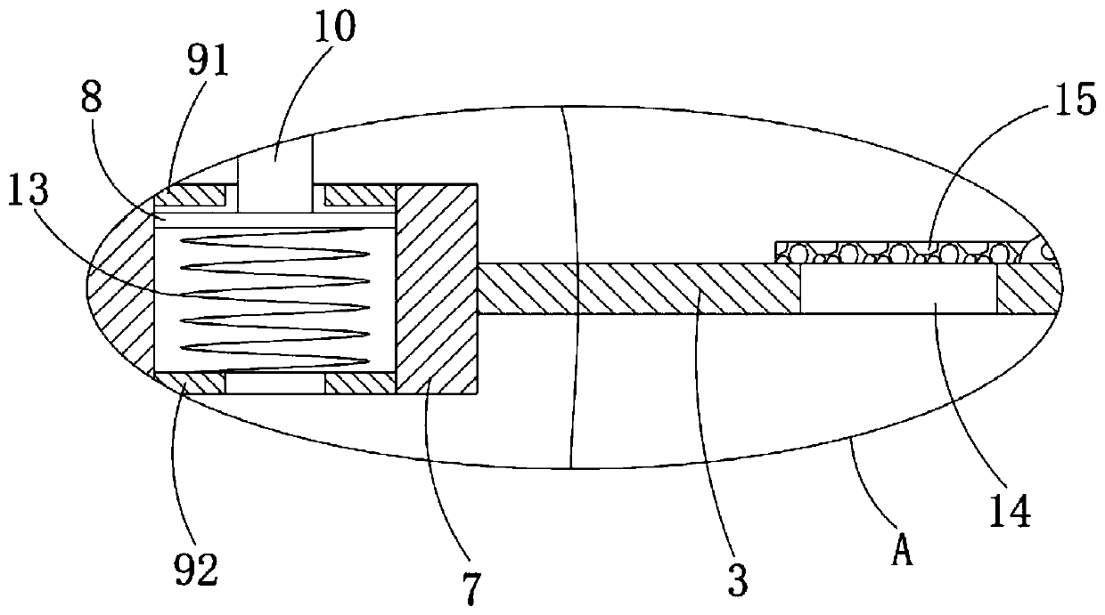
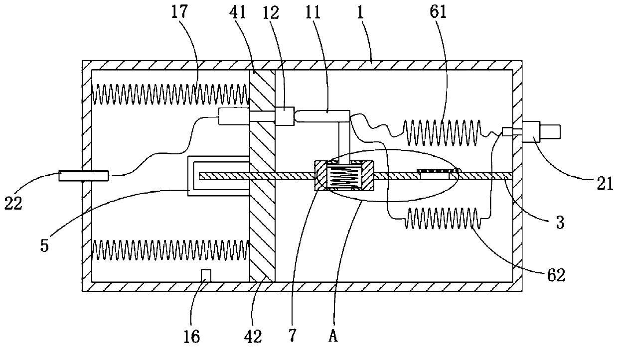
[0020] refer to Figure 1-2 , a short-circuit-proof resettable fuse, an insulating case 1, a square cavity is arranged inside the insulating case 1, and a first terminal 21 and a second terminal are respectively fixedly connected to the two ends of the insulating case 1 22. The interior of the insulating housing 1 is fixedly connected with a partition 3, and the partition 3 and the inner wall of the insulating housing 1 are jointly sealed and slidingly connected with a first piston plate 41 and a second piston plate 42, and the first piston plate 41 and the second piston The plates 42 are located on both sides of the partition plate 3. The first piston plate 41 and the second piston plate 42 are fixedly connected with a synchronous piece 5, which is a U-shaped plate for ensuring the synchronous movement of the two piston plates.

[0021] The synchronization member 5 is located on the side of the first piston plate 41 close to the second terminal 22, and a plurality of second s...


PUM


Abstract

The invention discloses a short-circuit-proof restorable fuse, which comprises an insulating shell with a square cavity inside. The two ends of the insulating shell are fixedly connected with a firstbinding post and a second binding post respectively. The inside of the insulating shell is fixedly connected with a partition plate. The partition plate and the inner wall of the insulating shell jointly seal and are connected in a sliding manner with a first piston plate and a second piston plate. When the current is too high due to the short circuit danger in the circuit, the heat generated by asecond resistance wire is much more than that of a first resistance wire, so that the air pressure on one side of the second resistance wire is higher than that on the other side. A rotating plate ispushed to rotate to make the air on one side of the second resistance wire flow to the other side, and the two piston plates are pushed to move to achieve a circuit breaking effect. After the whole device is cooled, a conductive column can not resume electrical connection with a third binding post, so that the occurrence of short circuit again is avoided. The staff should check whether there is ashort circuit before manually replacing the fuse.

Description

technical field [0001] The invention relates to the field of electrical technology, in particular to a resettable fuse for preventing short circuit. Background technique [0002] In the power system, it is usually necessary to set a fuse to prevent the circuit from being damaged due to excessive current in the power system; current fuses mainly include disposable fuses and resettable fuses; for disposable fuses, once blown, It needs to be replaced as a whole, which is very inconvenient for ordinary residents; and for the current recoverable fuse, the main form is a bimetal thermal relay, and its on-off parts are composed of bimetal with different thermal deformation coefficients. If it is too large, when the temperature of the bimetal strip is too high, the bimetal strip will break contact due to deformation, and then turn it on after cooling; because it directly realizes the on-off through the deformation of the switch part itself, therefore, in the long-term use process ,...

Claims


Application Information

Patent Timeline
Patent Type & Authority Applications(China)
IPC IPC(8): H01H71/14
CPCH01H71/14
Inventor 李院花
Owner 美尔森电气系统(浙江)有限公司
Why Eureka
Try Eureka